CASE SV212D Tier 4B (final) Vibratory Roller Service Repair Manual Instant Download (DDDS212DNHWTB3010 and above)
CASE SV212D Tier 4B (final) Vibratory Roller Service Repair Manual Instant Download (DDDS212DNHWTB3010 and above)
Download Presentation

Please find below an Image/Link to download the presentation.
The content on the website is provided AS IS for your information and personal use only. It may not be sold, licensed, or shared on other websites without obtaining consent from the author. If you encounter any issues during the download, it is possible that the publisher has removed the file from their server.
You are allowed to download the files provided on this website for personal or commercial use, subject to the condition that they are used lawfully. All files are the property of their respective owners.
The content on the website is provided AS IS for your information and personal use only. It may not be sold, licensed, or shared on other websites without obtaining consent from the author.
E N D
Presentation Transcript
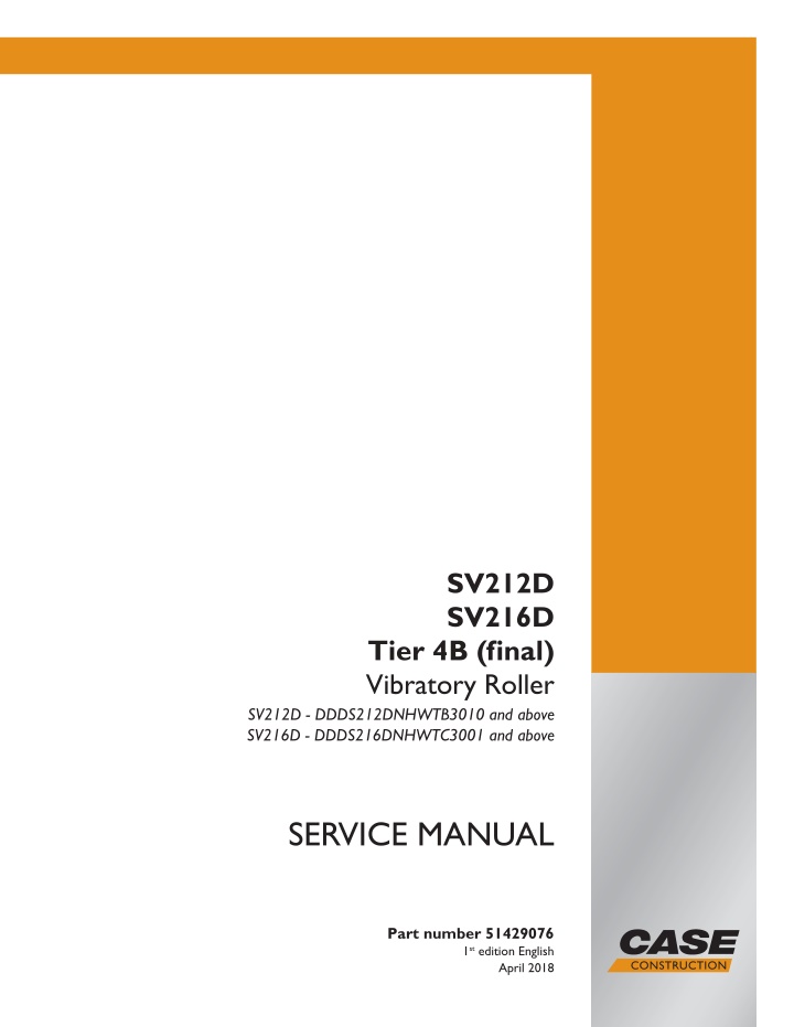
SV212D SV216D Tier 4B (final) Vibratory Roller SV212D - DDDS212DNHWTB3010 and above SV216D - DDDS216DNHWTC3001 and above SERVICE MANUAL Printed in U.S.A. Part number 51429076 1st edition English 2018 CNH Industrial America LLC. All Rights Reserved. Case is a trademark registered in the United States and many other countries, owned or licensed to CNH Industrial N.V., April 2018 its subsidiaries or affiliates.
Contents INTRODUCTION Engine....................................................................................... 10 [10.001] Engine and crankcase ............................................................. 10.1 [10.400] Engine cooling system ............................................................. 10.2 Hydrostatic drive......................................................................... 29 [29.218] Pump and motor components...................................................... 29.1 [29.202] Hydrostatic transmission ........................................................... 29.2 Brakes and controls .................................................................... 33 [33.110] Parking brake or parking lock ...................................................... 33.1 Hydraulic systems....................................................................... 35 [35.000] Hydraulic systems.................................................................. 35.1 [35.300] Reservoir, cooler, and filters........................................................ 35.2 [35.100] Main lift system..................................................................... 35.3 [35.741] Dozer blade cylinders .............................................................. 35.4 [35.995] Compaction/vibration hydraulic system ............................................ 35.5 Frames and ballasting................................................................. 39 [39.100] Frame .............................................................................. 39.1 [39.500] Vibratory roller...................................................................... 39.2 Steering..................................................................................... 41 [41.101] Steering control .................................................................... 41.1 [41.200] Hydraulic control components...................................................... 41.2 [41.206] Pump............................................................................... 41.3 [41.216] Cylinders ........................................................................... 41.4 Wheels...................................................................................... 44 [44.520] Rear wheels........................................................................ 44.1 [44.160] Compaction drums ................................................................. 44.2 51429076 03/04/2018
Cab climate control..................................................................... 50 [50.100] Heating............................................................................. 50.1 [50.200] Air conditioning..................................................................... 50.2 Electrical systems....................................................................... 55 [55.000] Electrical system ................................................................... 55.1 [55.100] Harnesses and connectors......................................................... 55.2 [55.201] Engine starting system............................................................. 55.3 [55.301] Alternator........................................................................... 55.4 [55.302] Battery.............................................................................. 55.5 [55.011] Fuel tank system ................................................................... 55.6 [55.512] Cab controls........................................................................ 55.7 [55.036] Hydraulic system control ........................................................... 55.8 [55.518] Wiper and washer system.......................................................... 55.9 [55.408] Warning indicators, alarms, and instruments .................................... 55.10 [55.DTC] FAULT CODES.................................................................. 55.11 Platform, cab, bodywork, and decals............................................. 90 [90.150] Cab................................................................................. 90.1 [90.114] Operator protections ............................................................... 90.2 [90.100] Engine hood and panels ........................................................... 90.3 [90.105] Machine shields and guards ....................................................... 90.4 51429076 03/04/2018
https://www.ebooklibonline.com Hello dear friend! Thank you very much for reading. Enter the link into your browser. The full manual is available for immediate download. https://www.ebooklibonline.com
INTRODUCTION 51429076 03/04/2018 1
INTRODUCTION Safety rules Personal safety This is the safety alert symbol. It is used to alert you to potential personal injury hazards. Obey all safety messages that follow this symbol to avoid possible death or injury. Throughout this manual you will find the signal words DANGER, WARNING, and CAUTION followed by special in- structions. These precautions are intended for the personal safety of you and those working with you. Read and understand all the safety messages in this manual before you operate or service the machine. DANGER indicates a hazardous situation that, if not avoided, will result in death or serious injury. WARNING indicates a hazardous situation that, if not avoided, could result in death or serious injury. CAUTION indicates a hazardous situation that, if not avoided, could result in minor or moderate injury. FAILURE TO FOLLOW DANGER, WARNING, AND CAUTION MESSAGES COULD RESULT IN DEATH OR SERIOUS INJURY. Machine safety NOTICE: Notice indicates a situation that, if not avoided, could result in machine or property damage. Throughout this manual you will find the signal word Notice followed by special instructions to prevent machine or property damage. The word Notice is used to address practices not related to personal safety. Information NOTE: Note indicates additional information that clarifies steps, procedures, or other information in this manual. Throughout this manual you will find the word Note followed by additional information about a step, procedure, or other information in the manual. The word Note is not intended to address personal safety or property damage. 51429076 03/04/2018 4
INTRODUCTION Personal safety General safety rules Use caution when you operate the machine on slopes. Raised equipment, full tanks and other loads will change the center of gravity of the machine. The machine can tip or roll over when near ditches and embankments or uneven surfaces. Never permit anyone other than the operator to ride on the machine. Never operate the machine under the influence of alcohol or drugs, or while you are otherwise impaired. When digging or using ground-engaging attachments, be aware of buried cables. Contact local utilities to determine the locations of services. Pay attention to overhead power lines and hanging obstacles. High voltage lines may require significant clearance for safety. Hydraulic oil or diesel fuel leaking under pressure can penetrate the skin, causing serious injury or infection. DO NOT use your hand to check for leaks. Use a piece of cardboard or paper. Stop the engine, remove the key, and relieve the pressure before you connect or disconnect fluid lines. Make sure that all components are in good condition. Tighten all connections before you start the engine or pres- surize the system. If hydraulic fluid or diesel fuel penetrates the skin, seek medical attention immediately. Continuous long term contact with hydraulic fluid may cause skin cancer. Avoid long term contact and wash the skin promptly with soap and water. Keep clear of moving parts. Loose clothing, jewelry, watches, long hair, and other loose or hanging items can become entangled in moving parts. Wear protective equipment when appropriate. DO NOT attempt to remove material from any part of the machine while it is being operated or while components are in motion. Make sure that all guards and shields are in good condition and properly installed before you operate the machine. Never operate the machine with shields removed. Always close access doors or panels before you operate the ma- chine. Dirty or slippery steps, ladders, walkways, and platforms can cause falls. Make sure these surfaces remain clean and clear of debris. A person or pet within the operating area of a machine can be struck or crushed by the machine or its equipment. DO NOT allow anyone to enter the work area. Raised equipment and/or loads can fall unexpectedly and crush persons underneath. Never allow anyone to enter the area underneath raised equipment during operation. Never operate the engine in enclosed spaces as harmful exhaust gases may build up. Before you start the machine, be sure that all controls are in neutral or park lock position. Start the engine only from the operator s seat. If you bypass the safety start switch, the engine can start with the transmission in gear. Do not connect or short across terminals on the starter solenoid. Attach jumper cables as described in the manual. Starting in gear may cause death or serious injury. Always keep windows, mirrors, all lighting, and Slow-Moving Vehicle (SMV) emblem clean to provide the best possible visibility while you operate the machine. Operate controls only when seated in the operator s seat, except for those controls expressly intended for use from other locations. 51429076 03/04/2018 5
INTRODUCTION Before you leave the machine: 1. Park the machine on a firm, level surface. 2. Put all controls in neutral or park lock position. 3. Engage the parking brake. Use wheel chocks if required. 4. Lower all hydraulic equipment Implements, header, etc. 5. Turn off the engine and remove the key. When, due to exceptional circumstances, you would decide to keep the engine running after you leave the operator s station, then you must follow these precautions: 1. Bring the engine to low idle speed. 2. Disengage all drive systems. WARNING Some components may continue to run down after you disengage drive systems. Make sure all drive systems are fully disengaged. Failure to comply could result in death or serious injury. 3. W0113A Shift the transmission into neutral. 4. Apply the parking brake. General safety rules specific to this machine Always have the machine moving when in vibration mode. The vibrator bearing only receives lubrication when the machine is moving. Do not change the vibration amplitude when driving. It is always necessary to stop first and then select a different amplitude. Do not adjust the heating valve control rod while driving. Do not roll and compact per bearing capacity of subsoil at such a distance from the edge of slopes or trenches, where hazard of a landslide or a shoulder breaking off (dropping) together with the machine could occur. Do not roll and compact with vibration at such a distance from walls, cuts, slopes, where their slip (slide) would happen because the operator and the machine could get covered with debris. Do not compact with vibration at such a distance from buildings or facilities and equipment within which the risk of them being damaged due to vibration transfer impact. General maintenance safety Keep the area used for servicing the machine clean and dry. Clean up spilled fluids. Service the machine on a firm, level surface. Install guards and shields after you service the machine. Close all access doors and install all panels after servicing the machine. Do not attempt to clean, lubricate, clear obstructions, or make adjustments to the machine while it is in motion or while the engine is running. Always make sure that working area is clear of tools, parts, other persons and pets before you start operating the machine. Unsupported hydraulic cylinders can lose pressure and drop the equipment, causing a crushing hazard. Do not leave equipment in a raised position while parked or during service, unless the equipment is securely supported. Jack or lift the machine only at jack or lift points indicated in this manual. 51429076 03/04/2018 6
INTRODUCTION Incorrect towing procedures can cause accidents. When you tow a disabled machine follow the procedure in this manual. Use only rigid tow bars. Stop the engine, remove the key, and relieve pressure before you connect or disconnect fluid lines. Stop the engine and remove the key before you connect or disconnect electrical connections. Scalding can result from incorrect removal of coolant caps. Cooling systems operate under pressure. Hot coolant can spray out if you remove a cap while the system is hot. Allow the system to cool before you remove the cap. When you remove the cap, turn it slowly to allow pressure to escape before you completely remove the cap. Replace damaged or worn tubes, hoses, electrical wiring, etc. The engine, transmission, exhaust components, and hydraulic lines may become hot during operation. Take care when you service such components. Allow surfaces to cool before you handle or disconnect hot components. Wear protective equipment when appropriate. When welding, follow the instructions in the manual. Always disconnect the battery before you weld on the machine. Always wash your hands after you handle battery components. 51429076 03/04/2018 7
INTRODUCTION Part identification - Machine components 1 RAIL17COM0076FA 1 2 3 4 5 6 7 8 9 10 11 12 13 14 Vibratory drum Drum frame Scraper Machine frame articulation joint Machine frame Axle Fuel tank Batteries Roll Over Protective System (ROPS) frame Hydraulic tank Cab or Canopy Hood Engine Radiator - Engine air cooler for intake manifold - Hydraulic systems cooler 15 16 17 18 19 20 21 23 24 25 26 27 28 Engine charge air cooler Driver s machine controls Travel hydraulic pump Vibration hydraulic pump Control hydraulic pump Catalytic converter Air filter Padfoot segments (optional) Hydraulic oil pressure filter Fuel filter Fuel filter with a water separator Engine oil filter Air pre-filter (optional) 51429076 03/04/2018 76
SERVICE MANUAL Engine SV212D SV216D 51429076 03/04/2018 10
Engine - Engine and crankcase Engine - Technical Data General technical data Engine type Working principle Charging Cooling type Preferred arrangement Number of cylinders Bore/stroke Total volume of cylinders Combustion process Injection system Exhaust gas recirculation Exhaust gas aftertreatment Dimensions TCD 4.1 L4 Four-stroke diesel engine Turbocharger with charge air cooling Water cooling Serial 4 101/126 4038 Direct injection Deutz Common Rail (DCR) External cooling Selective catalytic reduction (SCR) and Diesel particle filter (DPF) 4 0,3/0,5 75 15 /120 15 1-3-4-2 left mm cm3 Valves per cylinder Valve clearance: suction/exhaust Setting with rotary angle disc Engine firing order Direction of rotation when looking at the flywheel Rated engine power according to ISO 14396 kw Rated speed Coolant volume (only engine without cooler / hoses and tubes) Permissible continuous coolant temperature Temperature difference between the coolant inlet/outlet Beginning of thermostat opening Thermostat fully open Lubricating oil replacement volume (including filter), industrial engines/agricultural technology Temperature of lubricating oil in oil sump, maximum Minimum lubricating oil pressure (low idle, warm engine) Permissible maximum temperature of combustion air downstream of the charge air cooler V-belt tension AVX V-belts (width: 13 mm) Grooved V-belt tensioning mm See the engine nameplate See the engine nameplate 5.9 min-1 l max. 110 4-8 C C 87 102 11.5* C C l 125 C kPa/bar 80/0.8 50 C Pre-tensioning/Re-tensioning 650 50/400 50 Automatic tensioning of the spring clamping cylinder 400/450 N Weight without cooling system according to DIN 70020-A, industrial engines/agricultural technology * The stated lubricating oil volumes apply to the standard version. Engines that deviate from the standard, e.g. different lubricating oil sumps/dipstick variants and/or special tilted versions, may have different lubricating oil volumes. The lubricating oil dipstick is always decisive. kg 51429076 03/04/2018 10.1 [10.001] / 3
Engine - Engine and crankcase Engine - Component identification Description of the engine and basic components Engine name plate 1 RAIL18COM0135AA Right side view: 1. Combustion air inlet 2. Grooved V-belt 3. Idler pulley 4. Fuel filter 5. Lubricating oil drain plug 6. Lubricating oil filter 7. Lubricating oil dipstick 8. Lubricating oil cooler 9. Injection distribution system 10. Lubricating oil filling 2 RAIL18COM0136AA 11. Crankcase ventilation Left side view 1. Combustion air inlet 2. Coolant drain 3. Coolant inlet 4. Exhaust outlet 5. Lubricating oil drain plug 3 RAIL18COM0137AA 51429076 03/04/2018 10.1 [10.001] / 4
Engine - Engine and crankcase 4 RAIL18COM0419FA Exhaust aftertreatment system 1. Feed pump 2. AdBlue tank 3. AdBlue line for AdBlue tank pre-heating and for feed- ing unit cooling 4. AdBlue line 5. NOx sensor 6. Feeding unit 7. NOx sensor 8. Exhaust temperature sensor 9. Pressure sensor 10. SCR catalytic converter 11. Differential pressure sensor 12. Exhaust temperature sensor 13. Diesel particulate filter 14. Throttle 51429076 03/04/2018 10.1 [10.001] / 5
Engine - Engine and crankcase Engine - Remove 1. Using the proper equipment, evacuate the air condi- tioning system. 2. Disconnect the connector and remove the hose from the filter dehydrator. 1 RAIL18COM0143AA 3. Remove the hose from the condenser. 2 RAIL18COM0144AA 4. Disconnect the connector and remove the hose from the compressor. 3 RAIL18COM0145AA 51429076 03/04/2018 10.1 [10.001] / 6
Engine - Engine and crankcase 5. Remove the hood. Remove nuts from rubber-metals of the cab. 4 RAIL18COM0140AA 6. Electro-hydraulic control: Take off the cover of the cab lifting switch. Lift the cab using the switch. 5 RAIL18COM0139AA 7. Use the disconnector to disconnect the battery. 6 RAIL18COM0139AA 51429076 03/04/2018 10.1 [10.001] / 7
Engine - Engine and crankcase 8. Remove the rubber gasket. 7 RAIL18COM0248AA 9. Remove the covers from the under carriage. 8 RAIL18COM0172AA 10. Drain the engine oil through the drain plug (1). NOTE: The drained oil volume is 15 L (4 US gal). 9 RAIL18COM0264AA 51429076 03/04/2018 10.1 [10.001] / 8
Engine - Engine and crankcase 11. Remove the drain hose from the oil tank bottom. 10 RAIL18COM0146AA 12. Remove the DEF/ADBLUE tank. 11 RAIL18COM0147AA 13. Loosen the lid of the expansion tank. 12 RAIL18COM0263AA 51429076 03/04/2018 10.1 [10.001] / 9
Engine - Engine and crankcase 14. Drain the engine coolant. NOTE: The drained coolant volume is 34 L (9 US gal). 13 RAIL18COM0264AA 15. Disassemble the combined cooler according to En- gine cooling system - Remove (10.400) 14 RAIL18COM0154AA 51429076 03/04/2018 10.1 [10.001] / 10
Engine - Engine and crankcase 16. 1. Remove the exhaust hoses (1). 2. Remove the SCR catalyst (2). 3. Remove the DOC catalyst (3). 4. Cover the turbocharger outlet (4). 15 RAIL18COM0148AA 16 RAIL18COM0149AA 17. 1. Disconnect the sensor (1). 2. Remove the hoses (2). 3. Remove the overflow hose (3). 4. Remove the expansion tank (4) 17 RAIL18COM0150AA 51429076 03/04/2018 10.1 [10.001] / 11
Suggest: If the above button click is invalid. Please download this document first, and then click the above link to download the complete manual. Thank you so much for reading
Engine - Engine and crankcase 18. Disconnect the suction hose. Disconnect the wiring from the sensors. 18 RAIL18COM0151AA 19. Remove the air filter with the bracket. 19 RAIL18COM0163AA 20. Remove the bushings. 20 RAIL18COM0157AA 51429076 03/04/2018 10.1 [10.001] / 12
https://www.ebooklibonline.com Hello dear friend! Thank you very much for reading. Enter the link into your browser. The full manual is available for immediate download. https://www.ebooklibonline.com

