CEPC Booster Errors Studies in EDR - Correction Process Overview
In this set of studies and simulations for the CEPC Booster, errors and corrections are explored in detail, focusing on the design, simulation, and correction processes. Key aspects covered include orbit correction, horizontal dispersion response matrix, energy adjustment, optics correction, and more. These findings provide valuable insights into enhancing the performance and stability of the accelerator system.

Uploaded on Feb 28, 2025 | 1 Views
Download Presentation

Please find below an Image/Link to download the presentation.
The content on the website is provided AS IS for your information and personal use only. It may not be sold, licensed, or shared on other websites without obtaining consent from the author.If you encounter any issues during the download, it is possible that the publisher has removed the file from their server.
You are allowed to download the files provided on this website for personal or commercial use, subject to the condition that they are used lawfully. All files are the property of their respective owners.
The content on the website is provided AS IS for your information and personal use only. It may not be sold, licensed, or shared on other websites without obtaining consent from the author.
E N D
Presentation Transcript
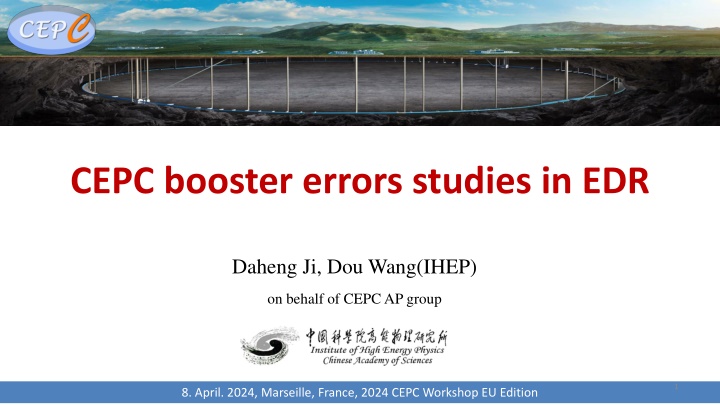
CEPC booster errors studies in EDR Daheng Ji, Dou Wang(IHEP) on behalf of CEPC AP group 1 8. April. 2024, Marseille, France, 2024 CEPC Workshop EU Edition
Content Content CEPC Booster Booster design Error and correction in TDR First turn commissioning simulation Further plan in the EDR Summary
Booster Design D. Wang, C. H. Yu, Y. M. Peng TME like structure (cell length=78m) Interleave sextupole scheme Emittance@120GeV=1.26nm Overall idea: uniform distribution for the Q Combined magnet (B+S) scheme possible Phase advance/cell: 100 (H) / 28 (V) Dispersion sup. Arc cell Half ring 3 2024 CEPC Workshop EU Edition
Error Set in Simulation Simulation based onAccelerator Toolbox(AT). Accuracy (m) 1e-7 Tilt (mrad) 10 Gain Offset w/ BBA (mm) 30e-3 Dipole Quadrupole Sextupole 3 cutoff Transverse shift X/Y ( m) 100 100 100 BPM(10Hz) 5% Longitudinal shift Z ( m) 100 150 150 Tilt about X/Y (mrad) 0.2 0.2 0.2 #BPM~2400 #Corrector~1200 Tilt about Z (mrad) 0.1 0.2 0.2 Nominal field 1e-3 2e-4 3e-4 dipole B1/B0 2 10-4 B2/B0 5 10-4 B3/B0 2 10-5 B4/B0 8 10-5 quadrupole B2/B1 3 10-4 B3/B1 2 10-4 B4/B1 1 10-4 B5/B0 2 10-5 B5/B1 1 10-4 B6/B0 8 10-5 B6/B1 5 10-5 B7/B0 2 10-5 B7/B1 5 10-5 B8/B0 8 10-5 B9/B0 2 10-5 B10/B0 8 10-5 B8/B1 5 10-5 B9/B1 5 10-5 B10/B1 5 10-5 4 2024 CEPC Workshop EU Edition
Correction Process Correction Process Orbit Correction + Horizontal dispersion Response Matrix 2-level iteration 1st Loop: 20%~100% Corrector 2nd Loop 30%~80% Singular Value Dispersion correction Energy adjustment by corrector 80um RMS in both plan Optics correction RM + LOCO Based on 30GeV simulation All quadrupole independent Dispersion correction included Coupling and vertical dispersion correction Mainly used for the simulation of beam polarization. (Z. Duan) Skew quadrupole magnets are arranged in both the dispersion free section and the arc section to correct coupling and vertical dispersion independently. the coupling control target being better than 0.5% 5 2024 CEPC Workshop EU Edition
Correction Process Correction Process Orbit Correction + Horizontal dispersion Response Matrix 2-level iteration 1st Loop: 20%~100% Corrector 2nd Loop 30%~80% Singular Value Dispersion correction Energy adjustment by corrector 80um RMS in both plan Optics correction RM + LOCO Based on 30GeV simulation All quadrupole independent Dispersion correction included Coupling and vertical dispersion correction Mainly used for the simulation of beam polarization. (Z. Duan) Skew quadrupole magnets are arranged in both the dispersion free section and the arc section to correct coupling and vertical dispersion independently. the coupling control target being better than 0.5% 6 2024 CEPC Workshop EU Edition
Correction Process Correction Process Orbit Correction + Horizontal dispersion Response Matrix 2-level iteration 1st Loop: 20%~100% Corrector 2nd Loop 30%~80% Singular Value Dispersion correction Energy adjustment by corrector 80um RMS in both plan Optics correction RM + LOCO Based on 30GeV simulation All quadrupole independent Dispersion correction included Coupling and vertical dispersion correction Mainly used for the simulation of beam polarization. (Z. Duan) Skew quadrupole magnets are arranged in both the dispersion free section and the arc section to correct coupling and vertical dispersion independently. the coupling control target being better than 0.5% RMS@30GeV X Y Orbit (mm) 0.080 0.080 Beta Beating(%) 0.8 0.38 Dispersion(mm) 2.7 3.5 7 2024 CEPC Workshop EU Edition
DA w/ Correction 30GeV 45GeV Tracking by SAD include errors (w. multipole errors) Include SR sawtooth orbit with taper@180GeV Include SR damping & fluctuation Off axis injection to collider On axis injection 180GeV 80GeV 120GeV Off axis injection to collider Off axis injection to collider 8 2024 CEPC Workshop EU Edition
Further Plan in the EDR Injection to storage: Filling the gap in the simulation of the entire process commissioning. First-turn, injection correction program, longitudinal parameter optimization program, etc. Fast measurement and correction: The application and evaluation of these fast correction programs for the CEPC Booster will be based on the TBT BPM measurement and correction program. Optimization of correction elements layout: Reducing costs while maintaining performance Dynamic errors and drift: jitter/vibration/ground drift Abnormal situations: Identification and handling in commissioning process feedback 9 2024 CEPC Workshop EU Edition
First Turn Commissioning First Turn Commissioning Recent simulation studies have been conducted on the initial beam commissioning of the CEPC Booster These studies can also serve as a reference for related research on the CEPC storage ring. Simulation settings: Physical aperture: 56mm BPM Accuracy and offset: 100um Other error settings are the same as those in ordinary error correction simulations. The injection beam jitter and beam distribution are taken into account. Based on the AT (Accelerator Toolbox) program. Using the response matrices of orbit, trajectory, working point, and injection beam derived from theoretical models. A similar correction process has already been applied to the HEPS (High Energy Photon Source) Booster and will be used in the beam tuning of the HEPS storage ring. Multi-turn Trajectory Correction, Injection Beam Trajectory Correction Single-turn Trajectory Correction 0 10 100 500 1000 10000 storaged Tune tuning, RF on TBT Optics Correction 10 2024 CEPC Workshop EU Edition RF Phase tuning
First Turn Commissioning First Turn Commissioning Multi-turn Trajectory Correction, Injection Beam Trajectory Correction Single-turn Trajectory Correction 0 10 100 500 1000 10000 storaged Tune tuning, RF Phase tuning RF on TBT Optics Correction Single-turn trajectory correction: Minimize the trajectory of the beam for the first 5 turns. Multi-turn trajectory correction: Average the beam trajectory over more than 5 turns to obtain an approximate closed orbit and correct it. Injection beam trajectory correction: Correct the coordinates of the injection beam at the injection point to reduce the oscillation of the injected beam. Tune adjustment: Calculate (Phased-CFT) and adjust the working point using the beam over 50 turns. RF parameters adjustment: Evaluate the beam energy variation with the average of the horizontal trajectory over each turn and adjust the RF parameters to reduce oscillation. Optics correction: Based on ICA, PCA. 11 2024 CEPC Workshop EU Edition
First Turn Commissioning First Turn Commissioning Multi-turn Trajectory Correction, Injection Beam Trajectory Correction Single-turn Trajectory Correction 0 10 100 500 1000 10000 storaged Tune tuning, RF Phase tuning RF on TBT Optics Correction Single-turn trajectory correction: Minimize the trajectory of the beam for the first 5 turns. Multi-turn trajectory correction: Average the beam trajectory over more than 5 turns to obtain an approximate closed orbit and correct it. Injection beam trajectory correction: Correct the coordinates of the injection beam at the injection point to reduce the oscillation of the injected beam. Tune adjustment: Calculate (Phased-CFT) and adjust the working point using the beam over 50 turns. RF parameters adjustment: Evaluate the beam energy variation with the average of the horizontal trajectory over each turn and adjust the RF parameters to reduce oscillation. Optics correction: Based on ICA, PCA. 12 2024 CEPC Workshop EU Edition
First Turn Commissioning First Turn Commissioning Multi-turn Trajectory Correction, Injection Beam Trajectory Correction Single-turn Trajectory Correction 0 10 100 500 1000 10000 storaged Tune tuning, RF Phase tuning RF on TBT Optics Correction Single-turn trajectory correction: Minimize the trajectory of the beam for the first 5 turns. Multi-turn trajectory correction: Average the beam trajectory over more than 5 turns to obtain an approximate closed orbit and correct it. Injection beam trajectory correction: Correct the coordinates of the injection beam at the injection point to reduce the oscillation of the injected beam. Tune adjustment: Calculate (Phased-CFT) and adjust the working point using the beam over 50 turns. RF parameters adjustment: Evaluate the beam energy variation with the average of the horizontal trajectory over each turn and adjust the RF parameters to reduce oscillation. Optics correction: Based on ICA, PCA. 13 2024 CEPC Workshop EU Edition
First Turn Commissioning First Turn Commissioning Multi-turn Trajectory Correction, Injection Beam Trajectory Correction Single-turn Trajectory Correction 0 10 100 500 1000 10000 storaged Tune tuning, RF Phase tuning RF on TBT Optics Correction Results indicate that after correction, approximately 30% of the particles survive for more than 10,000 turns. This can meet the needs of subsequent more detailed corrections, forming a complete process with previous simulation correction results. The algorithm is still undergoing optimization. The research still lacks many details, with some conditions such as the quality of the injection beam and more detailed physical apertures being updated and iterated. 14 2024 CEPC Workshop EU Edition
Further Plan in the EDR Injection to storage: Filling the gap in the simulation of the entire process commissioning. First-turn, injection correction program, longitudinal parameter optimization program, etc. Fast measurement and correction: The application and evaluation of these fast correction programs for the CEPC Booster will be based on the TBT BPM measurement and correction program. Optimization of correction elements layout: Reducing costs while maintaining performance Dynamic errors and drift: jitter/vibration/ground drift Abnormal situations: Identification and handling in commissioning process feedback 15 2024 CEPC Workshop EU Edition
Summary Summary For the existing error simulation settings, the corrected TME structure Lattice design (TDR) can meet the aperture requirements at various energy levels. If the Lattice design needs modification, the existing correction process can promptly provide simulation results and an assessment of the Lattice's robustness. In the EDR research plan, there is a focus on the needs of the actual machine. The initial beam commissioning study (starting from the first turn...) has essentially completed its algorithm, and correction attempts aimed at 10000 turns can be successfully accomplished. The correction algorithm still has room for optimization. Subsequent related research includes the accumulation of Seeds; iteration between the design and simulation results of injection beams, hardware errors, physical apertures, etc. Other research directions in the EDR plan are also ongoing, and the plan itself is continuously being supplemented and refined. 16 2024 CEPC Workshop EU Edition
Thanks for your attention!