CEPC Vacuum Chamber Design Comparison
Review the CEPC vacuum chamber design with photon absorbers in comparison with the TDR vacuum design. Explore the radiation shielding structure, water cooling design, and implications of the absorbers. Consider the complexity of the structure, machining requirements, impedance effects, and potential risks. Recommendations include conducting prototypes to assess feasibility.
Download Presentation

Please find below an Image/Link to download the presentation.
The content on the website is provided AS IS for your information and personal use only. It may not be sold, licensed, or shared on other websites without obtaining consent from the author. If you encounter any issues during the download, it is possible that the publisher has removed the file from their server.
You are allowed to download the files provided on this website for personal or commercial use, subject to the condition that they are used lawfully. All files are the property of their respective owners.
The content on the website is provided AS IS for your information and personal use only. It may not be sold, licensed, or shared on other websites without obtaining consent from the author.
E N D
Presentation Transcript
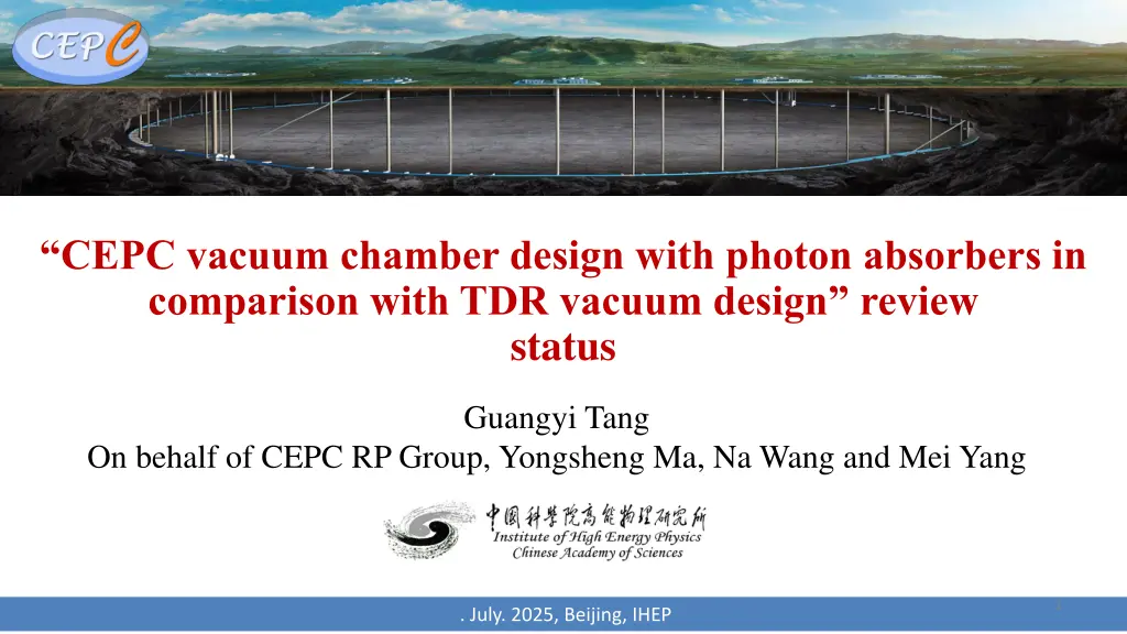
CEPC vacuum chamber design with photon absorbers in comparison with TDR vacuum design review status Guangyi Tang On behalf of CEPC RP Group, Yongsheng Ma, Na Wang and Mei Yang 1 . July. 2025, Beijing, IHEP
Committee member and presentation Committee member: Radiation protection: Adolfo Esposito (INFN), James C. Liu (SLAC), Markus Widorski (CERN) Vacuum: Roberto Kersevan (CERN), Kyo Shibata (KEK) Magnet: Mika Masuzawa (KEK) Presentation: Verification of the TDR vacuum chamber shielding design in comparison with antechamber vacuum system with photon absorbers review: Introduction CEPC vacuum chamber design with photon absorbers in comparison with TDR vacuum design Radiation shielding structure and water cooling design of CEPC collider magnet Verification of the TDR vacuum chamber shielding design in comparison with antechamber vacuum system with photon absorbers
Verification of the TDR vacuum chamber shielding design in comparison with antechamber vacuum system with photon absorbers review: Introduction CEPC overview CEPC TDR radiation protection overview Magnet insulation lead shielding Collider dump Linac dumps and bulk shielding Residual nuclei production Charge to review committee
CEPC vacuum chamber design with photon absorbers in comparison with TDR vacuum design Preview of CEPC vacuum system SR pathway diagram Vacuum chamber design of collider in TDR Structure of vacuum chamber with absorbers Mechanical adaption with magnets Design of Absorber Impedance of absorbers Conclusion
CEPC vacuum chamber design with photon absorbers in comparison with TDR vacuum design Conclusion The structure of vacuum chamber will be more complex, bad to NEG coating process; The structure of BPM, RF shielding bellows will be more complex but acceptable; The space for absorber needs to be considered, and requiring good machining and installation accuracy; The impedance increase due to the absorbers are less than 5% of the total budget acceptable from the instabilities; Lots risks of vacuum chamber with absorbers due to the welding between beam pipe and absorbers; Prototypes should be carried out to access its feasibility.
Radiation shielding structure and water cooling design of CEPC collider magnet Arc shielding design for Collider magnets in TDR Radiation Water Cooling Design of CEPC Collider Magnets Distribution of synchrotron radiation deposition Thermal analysis in DAD without water cooling Water cooling design for DAD radiation deposition Water cooling design for DAQ radiation deposition DAD modification for Synchrotron Radiation Absorber Summary
Radiation shielding structure and water cooling design of CEPC collider magnet Summary Cooling with stainless steel water-cooled tubes can significantly reduce the temperature rise of magnets and lead, and reduce the ventilation load so that the temperature in tunnel is stable. Lead shielding all along the arc region with cooling is feasible to reduce the temperature rise of the magnet by further increasing the contact surface New types of dipole and quadrupole compatible with photon absorber are finished. The cost is same with TDR types and power increases 10% for new types dipole. Further evaluation is needed for the temperature rise and water cooling design with photon absorbers. Further structural analysis is needed for the photon absorber scheme.
Verification of the TDR vacuum chamber shielding design in comparison with antechamber vacuum system with photon absorbers Design criteria and photon absorber @FCC CEPC TDR shielding scheme v.s. photon absorber scheme Prompt dose level in the tunnel for TDR scheme Protection of radiation-sensitive equipment Cables, electronics, optical fiber Induced dose level in the tunnel for TDR scheme TDR shielding scheme v.s. photon absorber scheme Prompt/Induced dose level in the tunnel Magnet shielding for photon absorber scheme Conclusion 8
Summary for the comparison Summary for the comparison Impact factor CEPC TDR scheme Photon absorber scheme Magnet coil insulation Epoxy resin insulation needs 25mm- thick lead. Epoxy resin insulation needs thicker lead around SR absorber Conceptual design is close to be finished, but the NEG coating process and lots risks of vacuum chamber with absorber due to welding should be carefully assess. The vacuum chamber and NEG coating process are well designed. vacuum The impedance increase due to the absorbers are less than 5% of the total budget, acceptable from the instabilities; The asymmetry of the structure will further introduce transverse monopolar impedance, this will be estimated. The impedance is well considered, and meets the requirement. Impedance Ra dia ton pro tec tio n Cables Lead/concrete shielding near inner wall On the wall without shielding Optical fiber Trench with concrete cover electronics In auxiliary tunnel. Or in the gap between supports with lead/concrete shielding 9
Summary for the comparison Summary for the comparison Impact factor CEPC TDR scheme Photon absorber scheme 1. Lead/concrete shielding, increases 30 ~ 830M CNY; 2. Cables, increases at most 790M CNY; 3. Cooling for magnets and lead, increase 100M CNY; 4. Trench and cover, estimating; 5.Gap between supports, probably not use; 1. Photon absorber, vacuum chamber, increase 1.3B CNY; 2. Less lead is used than TDR scheme, decrease -100M CNY; 3. Cooling for absorber and lead, estimating; 4. BPM, estimating; 2. Trench and cover, estimating; 3.Gap between supports, probably not use/ Cost Total: 920M ~1920M+ CNY Total: 1200M+ CNY The support of lead in the magnet and cooling; The arrangement of lead/concrete near the inner wall Manufacturing photon absorber. The support of lead in the magnet and cooling Engineering design 10
Verification of the TDR vacuum chamber shielding design in comparison with antechamber vacuum system with photon absorbers Conclusion: For TDR scheme: The induced dose-eq levels are safe for a long-time work in the tunnel, except the short-cooling-after- ttbar-operation case in which it is safe for a short-time work (10h). Radiation level in the auxiliary tunnel is safe for electronics, radiation level around inner wall with shielding is safe for cables, radiation level in the trench is safe for optical fiber. The preliminary thermal analysis shows the water cooling can bring 72% deposited heat out so that the ventilation load is acceptable and the temperature in tunnel is stable. Based on the addition of inner shielding walls in the new tunnel, the rational design of trench covers, and the maze of the auxiliary tunnel, TDR is feasible, with cost increasing 830M ~1830M CNY + cost of trench covers. For photon absorber scheme, the NEG coating process and lots risks of vacuum chamber with absorber due to welding should be carefully assess; The epoxy resin insulation in magnet cannot withstand with 38mm lead shielding, we are trying to add more shielding to protect insulation. The induced dose-eq levels are safe for a long-time work in the tunnel. Radiation level in the auxiliary tunnel is safe for electronics, radiation level around inner wall is safe for cables, radiation level in the trench is safe for optical fiber. The thermal analysis is on-going. 11
Verification of the TDR vacuum chamber shielding design in comparison with antechamber vacuum system with photon absorbers Conclusion: For photon absorber scheme, Once the NEG coating process, vacuum welding process and magnet insulation shielding design are ready, photon absorber scheme will be feasible, with cost increasing 1200M CNY + cost of trench covers, BPM and cooling system. The photon absorber scheme has not been well optimized. However, the radiation level @ttbar operation using photon absorber scheme is better than using TDR scheme, meanwhile the radiation level @Z operation using photon absorber scheme is not. For both photon absorber scheme and TDR scheme, challenges in design water cooling system and supporting exist. We are currently planning a series of experiments, including the process for fixing cooling water pipes on lead, the thermal conductivity between lead and cooling water pipe, and the aging test for composite insulation layer cables. Thank you 12


