Characteristics and Features of ADC in PIC Microcontroller
Learn about the conversion of analog signals to digital data using ADC in PIC microcontroller. Explore the resolution, conversion time, digital data output, and features of ADC in PIC18F4550.

Download Presentation

Please find below an Image/Link to download the presentation.
The content on the website is provided AS IS for your information and personal use only. It may not be sold, licensed, or shared on other websites without obtaining consent from the author. If you encounter any issues during the download, it is possible that the publisher has removed the file from their server.
You are allowed to download the files provided on this website for personal or commercial use, subject to the condition that they are used lawfully. All files are the property of their respective owners.
The content on the website is provided AS IS for your information and personal use only. It may not be sold, licensed, or shared on other websites without obtaining consent from the author.
E N D
Presentation Transcript
PIC Microcontroller Prof. Ashvini Kulkarni Assistant Professor Department of Electronics & Telecommunication Hope Foundation s International Institute of Information Technology, I IT www.isquareit.edu.in 1
Characteristics of ADC PIC 18 ADC features PIC 18 ADC control registers Hope Foundation s International Institute of Information Technology, I IT, P-14 Rajiv Gandhi Infotech Park, Hinjawadi, Pune - 411 057 Tel - +91 20 22933441 / 2 / 3 | Website - www.isquareit.edu.in ; Email - info@isquareit.edu.in 2
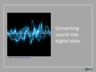
Analog signal is converted into a digital data that can be processed using a digital computer. Types of ADC: Slope and double-slope type Flash type Successive approximation Types of ADC: Hope Foundation s International Institute of Information Technology, I IT, P-14 Rajiv Gandhi Infotech Park, Hinjawadi, Pune - 411 057 Tel - +91 20 22933441 / 2 / 3 | Website - www.isquareit.edu.in ; Email - info@isquareit.edu.in 3
Characteristics of ADC[2]: 1. Resolution: ADC has n- bit resolution(where n=8,10,12,16,24 bits) Higher the resolution smaller the step size If ADC has 8 bit resolution means 2^8= 256(No. of steps) Applied voltage is Vref=5v then 5/256=19.53 mv (step size) 2. Conversion time: The time it takes for the converting analog input to digital output Vref:It is input voltage used for the reference voltage Vref/no. of steps(Vref is responsible for step size) Hope Foundation s International Institute of Information Technology, I IT, P-14 Rajiv Gandhi Infotech Park, Hinjawadi, Pune - 411 057 Tel - +91 20 22933441 / 2 / 3 | Website - www.isquareit.edu.in ; Email - info@isquareit.edu.in Characteristics of ADC[2]: 4
Characteristics of ADC: 3. Digital data output: 8 bit ADC, we have 8bit digital data output of D0 D7 Dout=Vin/step size[2] Characteristics of ADC: Hope Foundation s International Institute of Information Technology, I IT, P-14 Rajiv Gandhi Infotech Park, Hinjawadi, Pune - 411 057 Tel - +91 20 22933441 / 2 / 3 | Website - www.isquareit.edu.in ; Email - info@isquareit.edu.in 5
Features of ADC 1) The ADC in PIC18F4550 is a successive approximation ADC with a resolution of 10 bits. 2) It has 10 input channels. Features of ADC Hope Foundation s International Institute of Information Technology, I IT, P-14 Rajiv Gandhi Infotech Park, Hinjawadi, Pune - 411 057 Tel - +91 20 22933441 / 2 / 3 | Website - www.isquareit.edu.in ; Email - info@isquareit.edu.in 6
Configuring Registers Configuring Registers The PIC18 Microcontroller - The A/D converter has the following registers[1]: A/D Control Register 0 (ADCON0) A/D Control Register 1 (ADCON1) A/D Control Register 2 (ADCON2) A/D Result High Register (ADRESH) A/D Result Low Register (ADRESL) Hope Foundation s International Institute of Information Technology, I IT, P-14 Rajiv Gandhi Infotech Park, Hinjawadi, Pune - 411 057 Tel - +91 20 22933441 / 2 / 3 | Website - www.isquareit.edu.in ; Email - info@isquareit.edu.in 7
Figure No. 1: Block diagram of ADC in PIC18f4550[1] Hope Foundation s International Institute of Information Technology, I IT, P-14 Rajiv Gandhi Infotech Park, Hinjawadi, Pune - 411 057 Tel - +91 20 22933441 / 2 / 3 | Website - www.isquareit.edu.in ; Email - info@isquareit.edu.in 8
Each port pin associated with the A/D converter can be configured as an analog input or as a digital I/O. When the A/D conversion is complete, the result is loaded into the ADRESH:ADRESL registers, the GO/DONE bit (ADCON0 register) is cleared and A/D Interrupt Flag bit, ADIF, is set. Hope Foundation s International Institute of Information Technology, I IT, P-14 Rajiv Gandhi Infotech Park, Hinjawadi, Pune - 411 057 Tel - +91 20 22933441 / 2 / 3 | Website - www.isquareit.edu.in ; Email - info@isquareit.edu.in 9
The analog reference voltage is software selectable to either the device s positive and negative supply voltage (VDD and VSS) or the voltage level on the RA3/AN3/VREF+ and RA2/AN2/VREF-/CVREF pins. Hope Foundation s International Institute of Information Technology, I IT, P-14 Rajiv Gandhi Infotech Park, Hinjawadi, Pune - 411 057 Tel - +91 20 22933441 / 2 / 3 | Website - www.isquareit.edu.in ; Email - info@isquareit.edu.in 10
Configure the A/D module: Configure analog pins, voltage reference and digital I/O (ADCON1) Select A/D input channel (ADCON0) Select A/D acquisition time (ADCON2) Select A/D conversion clock (ADCON2) Turn on A/D module (ADCON0) 2. Configure A/D interrupt (if desired): Clear ADIF bit Set ADIE bit Set GIE bit 3. Wait the required acquisition time (if required). Start conversion Set GO/DONE=1 bit in (ADCON0 register) 1. Hope Foundation s International Institute of Information Technology, I IT, P-14 Rajiv Gandhi Infotech Park, Hinjawadi, Pune - 411 057 Tel - +91 20 22933441 / 2 / 3 | Website - www.isquareit.edu.in ; Email - info@isquareit.edu.in 11
5. Wait for A/D conversion to complete, by either: Polling for the GO/DONE bit to be cleared OR Waiting for the A/D interrupt 6. Read A/D Result registers (ADRESH:ADRESL); clear bit ADIF, if interrupt bit is set. 7. For next conversion, go to step 1 or step 2, as required. Hope Foundation s International Institute of Information Technology, I IT, P-14 Rajiv Gandhi Infotech Park, Hinjawadi, Pune - 411 057 Tel - +91 20 22933441 / 2 / 3 | Website - www.isquareit.edu.in ; Email - info@isquareit.edu.in 12
[1] Microchip datasheet of PIC18F2455/2550/4455/4550 [2] Muhamad Ali Mazidi,Rolind D Mckinly, PIC microcontroller and embedded systems Pearson publication. Hope Foundation s International Institute of Information Technology, I IT, P-14 Rajiv Gandhi Infotech Park, Hinjawadi, Pune - 411 057 Tel - +91 20 22933441 / 2 / 3 | Website - www.isquareit.edu.in ; Email - info@isquareit.edu.in 13
For further information please contact Ashvini Kulkarni Department of Electronics & Telecommunication Hope Foundation s International Institute of Information Technology, I IT Hinjawadi, Pune 411 057 Phone - +91 20 22933441 www.isquareit.edu.in | ashvinik@isquareit.edu.in | info@isquareit.edu.in 14