Characteristics and Performance of Power Transmission Lines
Transmission lines are crucial components in power systems that require a deep understanding of their characteristics and performance. The analysis is often done on a per-phase basis using two-port network representations with A, B, C, and D parameters. These parameters, which depend on line parameters like R, L, C, and G, help in determining the behavior of transmission lines for various lengths and voltages. The distinction between lumped and distributed parameters is essential for accurate modeling, especially for long transmission lines. This content delves into the significance of these parameters, symmetrical networks, and the impact of line length on parameter choices, offering insights into optimizing power transmission systems.

Download Presentation

Please find below an Image/Link to download the presentation.
The content on the website is provided AS IS for your information and personal use only. It may not be sold, licensed, or shared on other websites without obtaining consent from the author.If you encounter any issues during the download, it is possible that the publisher has removed the file from their server.
You are allowed to download the files provided on this website for personal or commercial use, subject to the condition that they are used lawfully. All files are the property of their respective owners.
The content on the website is provided AS IS for your information and personal use only. It may not be sold, licensed, or shared on other websites without obtaining consent from the author.
E N D
Presentation Transcript
Chapter 4: Characteristics and performance of power transmission lines 1
Representation of Transmission Lines Transmission lines are normally operated with a balanced three phase load. The analysis can therefore proceed on a per phase basis. ?? ?? Two Port Network ? ? ?? ?? ? ? 2
It is convenient to represent the single phase equivalent of a transmission line by the two-port network, where in the sending end voltage VS and current IS are related to the receiving end voltage VR and current IR through A, B, C and D parameters as: ??= ???+ ??? ????? ??= ???+ ??? ??? In matrix form: ?? ?? ?? ?? =? ? ? ? 3
A, B, C and D are the parameters that depend on the line parameters R, L, C and G. The ABCD parameters are, in general complex numbers. A and D are dimensionless. B has units of Ohms and D has units of Siemens. The following identity holds true for ABCD constants: ?? ?? = 1 For symmetrical network A and D are equal. 4
To avoid confusion between total series impedance and series impedance per unit length, the following notation is used: Series impedance per unit length: ? = ? + ??? /m Shunt admittance per unit length: ? = ? + ??? ?/m Total series impedance: ? = ?? Total shunt admittance: ? = ?? S Line length in meter: ? m 5
The parameters of transmission lines which are discussed in chapter three are uniformly distributed along the lines. For lines of short and medium length we can use lamped parameters with good accuracy. For long transmission lines the parameters must be taken as distributed parameters. Because approximating the uniformly distributed parameters of long lines to lamped parameters results considerable error. 6
Short Transmission Line (< 80km) Capacitance may be ignored with out much error if the lines are less than 80 km long or if the voltage is not over 66 kV. ?? ?? ?? ?? =1 ? 1 0 7
The phasor diagram for the short line is shown below for lagging current. 8
Voltage Regulation Voltage regulation of transmission lines may be defined as the percentage change in voltage at the receiving end of the line expressed as percentage of full load voltage in going from no-load to full-load. ???? ???? ???? % ??????? ?????????? = 100 Where: ????= magnitude of no-load receiving end voltage ????= magnitude of full-load receiving end voltage 9
At no load, ??= 0,??= ???? and: ????= ?? ? Therefore, ?? ? ???? ? ???? % ??????? ?????????? = 100 For a short line ? = 1, ????= ?? ?? ?? ?? % ??????? ?????????? = 100 10
Medium Transmission Line (80 km < l < 240km) Transmission lines more than 80 km long and below 250 km in length are treated as medium lines, and the line charging current becomes appreciable and the shunt capacitance must be considered. Medium lines can be represented sufficiently well by R, L and C as lumped parameters with: Half the capacitance to neutral of the line lumped at each end of the equivalent circuit ( -model) or Half of the series impedance lumped at each side of the line (T- model). 11
T-model 1 +?? ? 1 +?? ?? ?? ?? ?? 2 4 = 1 +?? ? 2 13
Long Transmission Line (> 250 km) I(x+ x) I(x) + + + + IS IR VS V(x+ x) V(x) VR Gen. Load _ _ _ _ x dx 14
Taking the limit as x approaches zero: Similarly, writing KCL equation for the circuit: Taking the limit as x approaches zero: 16
If we differentiate again the above equation: This equation is a linear, second order, homogeneous differential equation with one unknown, V(x). By inspection, its solution is: ?(?) = ?1???+ ?2? ?? volts 17
Where ?1 and ?2are integration constants and ? = ?, whose units are m-1, is called propagation constant and is given by: ? = ? + ?? = ?? ? 1 ?? The real part, ? is known as the attenuation constant, and the imaginary part, ? is known as the phase constant. 18
For the current: ??(?) ?? = ??1??? ??2? ??= ??(?) Solving for I(x): ?(?) =?1??? ?2? ?? ?? ??= ? ??= ?? ??= 19
I(x) becomes: ?(?) =?1??? ?2? ?? ?? ?? and is called the characteristics Where ??= impedance. Next, the integration constants ?1 and ?2 are evaluated from the boundary conditions. 20
When ? = 0,? ? = ?? and ? ? = ??, from the above voltage and current equations, we get: ??= ?1+ ?2 1 ?? ??= (?1 ?2) Solving these equations, we obtain: ?1=??+ ???? 2 ?2=?? ???? 2 21
Substituting the values of ?1 and ?2 into the voltage and current equations, we obtain: ? ? =(??+ ????) 2 ? ? =(??+ ????) 2?? ???+(?? ????) ? ?? 2 ??? (?? ????) ? ?? 2?? The equations can be rearranged as follows: ? ? =(???+ ? ??) 2 ? ? =(??? ? ??) 2?? (??? ? ??) 2 ??+ ?? ??+(???+ ? ??) ?? ?? 2 22
? ? = cosh ?? ??+ ??sinh(??)?? 1 ?? ? ? = sinh ?? ??+ cosh(??)?? Our interest is in the relation between the sending end and the receiving end of the line. Therefore, when ? = ?,? ? = ??and ? ? = ??. The result is: ??= cosh ?? ??+ ??sinh(??)?? 1 ?? ??= sinh ?? ??+ cosh(??)?? 23
Therefore, ABCD constants are: ? = cosh(??) ? = ??sinh(??) 1 ?? ? = cosh(??) ? = sinh(??) 24
The Equivalent Circuit of a Long Line The nominal- circuit does not represent a transmission line exactly because it does not account for the parameters of the line being uniformly distributed. The discrepancy between the nominal- and the actual line becomes larger as the length of line increases. 25
It is possible, however, to find the equivalent circuit of a long transmission line and to represent the line accurately, in so far as ends of the line are concerned, by a network of lumped parameters. 26
Power Flow through Transmission Lines Equations for power can be derived in terms of ABCD constants. The equations apply to any network of two ports. Letting: 29
We obtain: The complex power at the receiving end is: The real and reactive power at the receiving end are: 30
Examination of the phasor diagrams shows that there is a limit to the power that can be transmitted to the receiving end of the line for specified magnitudes of sending- and receiving-end voltages. An increase in power delivered means that the point k will move along the circle until the angle ( - ) is zero; that is, more power will be delivered until = . Further increase in results in less power received. 32
The maximum power is: The load must draw a large leading current to achieve the condition of maximum power received . Usually, operation is limited by keeping: 1. less than about 350 (Stability limit) ?? ?? equal to or greater than 0.95 (Voltage drop limit) 3. For short lines thermal ratings limit the loading (I2R limit) 2. 33
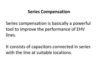
Reactive Compensation of Transmission Lines The performance of transmission lines, especially those of medium length and longer, can be improved by reactive compensation of a series or parallel type. Series compensation consists of a capacitor bank placed in series with each phase conductor of the line. Shunt compensation refers to the placement of inductors from each line to neutral to reduce partially or completely the shunt susceptance of a high-voltage line, which is particularly important at light loads when the voltage at the receiving end may otherwise become very high. 34
Series compensation reduces the series impedance of the line, which is the principal cause of voltage drop and the most important factor in determining the maximum power which the line can transmit. The desired reactance of the capacitor bank can be determined by compensating for a specific amount of the total inductive reactance of the line. This leads to the term "compensation factor," which is defined by ??, where ?? is the capacitive reactance of the series capacitor bank per phase and ?? is the total inductive reactance of the line per phase. ?? 35
When the nominal- circuit is used to represent the line and capacitor bank and if only the sending- and receiving-end conditions of the line are of interest, the physical location of the capacitor bank along the line is not taken in to account. However, when the operating conditions along the line are of interest, the physical location of the capacitor bank must be taken into account. 36
This can be accomplished most easily by determining ABCD constants of the portions of line on each side of the capacitor bank and by representing the capacitor bank by its ABCD constants. The equivalent constants of the combination (actually referred to as a cascaded connection) of line capacitor - line can then be determined. 37
Ferranti Effect During light load or no-load condition, receiving end voltage is greater than sending end voltage in long transmission line or cable. This happens due to very high line charging current. This phenomenon is known as ferranti effect. A chrged open circuit line draws significant amount of current due to capacitive effect of the line. This is more in high voltage long transmission lines. 38


")


")


 becomes:")


??")