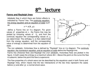
Choked Two-Phase Flow with Account of Discharge Line Effects
This scientific study focuses on predicting source exit conditions for two-phase discharge scenarios. The development of an engineering tool incorporating discharge line friction and cross-sectional area changes is explored through mathematical formulation and numerical methods. Various flash models are implemented and tested against experimental data to provide insights for future work in this area.
Download Presentation

Please find below an Image/Link to download the presentation.
The content on the website is provided AS IS for your information and personal use only. It may not be sold, licensed, or shared on other websites without obtaining consent from the author.If you encounter any issues during the download, it is possible that the publisher has removed the file from their server.
You are allowed to download the files provided on this website for personal or commercial use, subject to the condition that they are used lawfully. All files are the property of their respective owners.
The content on the website is provided AS IS for your information and personal use only. It may not be sold, licensed, or shared on other websites without obtaining consent from the author.
E N D
Presentation Transcript
Thermodynamics I Chapter 6 Entropy Mohsin Mohd Sies Fakulti Kejuruteraan Mekanikal, Universiti Teknologi Malaysia
Entropy (Motivation) The preferred direction implied by the 2ndLaw can be better understood and quantified by the concept of entropy. Entropy quantifies the 2ndLaw and imposes the direction of processes. Here we will study entropy and how processes will proceed only in the direction of increasing entropy.
Clausius Inequality TH QH QH W Wirrev Erev Eirrev QL QL,irrev TL Consider two heat engines between the same temperatures
Q Consider of the whole cycle T (a) Erev Q Q Q = H L T T T rev H L 1 1 = Q Q H L T T H L Q Q = H L T T H L = 0 Q = 0 T rev
Q > Q (b) Eirrev irrev L, L Q = Q + Q irrev L, L
Combined to be: = 0 < 0 > 0 impossible if reversible if irreversible
ENTROPY 2 B A 1 2 1 Let's call this property entropy, S [kJ/K] Q Q Q 1 2 = + = 0 T T T rev A B Q dS T rev 2 1 Q Q 1 2 = T T Does not depend on path; thermodynamic property! A B 2 Q 1 = T B
Entropy , S = extensive property [kJ/K] Specific entropy, s = intensive property [kJ/kg.K] Q 2 2 = = dS S S 2 1 T 1 1 rev We have actually defined entropy change From statistical thermodynamics, entropy ~ measure of molecular disorder Work is an ordered form of energy (High quality) No entropy transfer along with work transfer Heat is a disordered form of energy (Low quality) Entropy is transferred along with heat transfer Entropy = zero for pure crystal at 0 K Third Law of Thermodynamics Entropy with a 0 K reference is called absolute entropy
T-ds Relations To find the relationship between Q and T so that the integration of Q/T can be performed - From the 1st Law (neglecting KE & PE) Q W = U rev = dU Q W rev = TdS Q rev pdV dU = TdS = pdV W rev dU = pdV + TdS du = pdv + Tds (a)
- From the definition of enthalpy pv u h + = = + vdp + dh du pdv dh = pdv vdp du From (a) Tds du = pdv + dh = pdv vdp pdv + dh = vdp Tds (b)
T-ds Relations du = pdv + Tds dh = vdp Tds du pdv & = + ds T T dh vdp = ds T T Can be used for S of any process (rev. & irrev.) Can be used for open & closed system
Entropy Change of Pure Substances Can be obtained from Tds Relations in conjunction with other thermodynamic relations For 2 phase substances like water and R-134a, use property tables S = S2 S1 For ideal gas, from Tds relations = du pdv du C dT v = + ds T T p R RT = = pv dT dv T v = + ds C R v T v Assume Cv=constant & integrate dT dv = + ds C R v T v T v = = + ln ln 2 2 s s s C R 2 1 v T v 1 1
dh vdp = ds Another relation, T T dT dp = = dh C dT ds C R p p T p v R = = pv RT dT dp = T p ds C R p T p Assume Cp =constant & integrate T p = = ln ln 2 2 s s s C R 2 1 p T p 1 1
Entropy change T v = = ln R + ln v 2 2 s s s C 2 1 T v 1 1 p T = = ln R ln p 2 2 s s s C 2 1 T p 1 1 Both equations give the same result Choose according to available data..
Isentropic Processes, S = 0 For ideal gases, with constant Cp & Cv T v = + = ln ln 0 2 2 s C R v T v 1 1 T v = ln ln 2 2 C R v T v 1 1 R C T R v v v = = ln ln ln 2 2 1 T C v v 1 1 2 v = C C R p v 1 k T v C = ln ln 2 1 p = k T v C 1 2 v R 1 k = T v 1 k = 2 1 C v T v 1 2
Another one T p = = ln ln 0 2 2 s C R p T p 1 1 T R p = ln ln 2 2 T C p 1 1 p R C p p = ln 2 p 1 1 k = C C R p k p v = ln 2 C 1 C R p p = = 1 v 1 C C C 1 k 1 k p p p T p k R k = 2 2 = T p C k 1 1 p
Combined to become 1 k k Isentropic process for ideal gas, constant Cp , Cv 1 k T p v = = 2 2 1 T p v 1 1 2
Work for Open Systems = pdv wB Reversible boundary work for closed systems Open system reversible work, from 1st Law (single inlet/outlet) ( ) ke ( ) = dh + d + d pe q w rev rev = Tds q rev ( ) ke ( ) Tds = dh vdp dh vdp = dh + d + d pe w rev = dh vdp q rev neglecting ke & pe, & rearrange; = vdp w rev 2 1 w = dp v Reversible work for open system rev
Increase in Entropy Principle For reversible processes, entropy of universe (system surrounding) doesn't change, it is just transferred (along with heat transfer) In real processes, irreversibilities cause entropy of universe to increase Heat reservoirs don't have irreversibility To simplify analysis, assume irreversibilities to exist only inside the system under study. Inside the system, entropy transfer and generation occur. 2 Irreversible cycle since one of the processes is irreversible irrev rev 1 From Clausius Inequality;
Rearrange 2 Q 1 S S < 2 1 T irrev 2 Q 1 S S > 2 1 T irrev Generalize for all processes = when rev > when irrev < impossible 2 Q 1 1 S S 2 T 2 Q 1 S S = + S Sgen=entropy generated = 0 when rev. > 0 when irrev. < 0 impossible 2 1 gen T
Entropy Generation for Closed System 2 T Q 1 S 1 2 gen S + = S b Transfer of entropy (T where Q is transferred, usually at boundary Change of system entropy Entropy generation
Sgen is the measure of irreversibilities involved during process = 0 S = + S S S gen total, universe surroundin g system S surrounding or system may decrease (-ve), but S total (surrounding + system) must be > 0 Entropy of universe always increases (Entropy increase principle) No such thing as entropy conservation principle For a process to occur, Sgen> 0
Entropy Generation for Closed System Q = = + S S S S 2 1 gen T b Q = + S S S 2 1 gen T b For multiple heat transfers at different temperatures Q n =1 j = + S S S 2 1 gen T j j
Entropy Generation for Closed System Q n dS = S j = + In rate form gen dt T 1 j j Q n = j = + dS S In differential form gen T 1 j j Sgen - depends on the process (friction, T etc.) - not a property
Entropy Generation for Open Systems Apart from heat, mass flows also carry entropy along with them mout sout CV min sin Qin Q = j = + + S S S S CV in out gen T 1 j j Q = j = + + S ms ms S CV in out gen T 1 j j
Entropy Generation for Open Systems CV min sin Qin Q dS =1 S j = + + CV m s m s in out gen dt T j j Rate of change of system entropy Rate of entropy generation Rate of entropy transfer
Steady Flow Process dm = = 0 CV m m in out dt dS = 0 CV dt Q dS = S j = + + CV m s m s i i o o gen dt T 1 j j Q = S j = + + 0 m s m s i i o o gen T 1 j j
Steady Flow Process single inlet/outlet; Q = S j = + + 0 ( ) m s s i o gen T 1 j j Q S j m = gen = + s s o i m T 1 j j
Reversible adiabatic process = isentropic process Isentropic is not necessarily reversible adiabatic Sgen = 0 Reversible process Produces Wmax Consumes Wmin
ISENTROPIC EFFICIENCIES OF STEADY-FLOW DEVICES Also known as Adiabatic Efficiency or 2nd Law Efficiency The isentropic process involves no irreversibilities and serves as the ideal process for adiabatic devices. Isentropic Efficiency of Turbines The h-s diagram for the actual and isentropic processes of an adiabatic turbine. 30
Isentropic Efficiencies of Compressors and Pumps When kinetic and potential energies are negligible Compressors are sometimes intentionally cooled to minimize the work input. The h-s diagram of the actual and isentropic processes of an adiabatic compressor. 31
Isentropic Efficiency of Nozzles If the inlet velocity of the fluid is small relative to the exit velocity, the energy balance is The h-s diagram of the actual and isentropic processes of an adiabatic nozzle. Then, A substance leaves actual nozzles at a higher temperature (thus a lower velocity) as a result of friction. 32
