Clocks, PLLs, and Synchronous Circuits in Circuit Design
Delve into the concepts of clocks, PLLs, and synchronous circuits in circuit design to manage glitches, delays, and timing requirements effectively. Learn about clock cycles, clock frequencies, and the significance of meeting timing requirements in electronic projects.

Download Presentation

Please find below an Image/Link to download the presentation.
The content on the website is provided AS IS for your information and personal use only. It may not be sold, licensed, or shared on other websites without obtaining consent from the author. If you encounter any issues during the download, it is possible that the publisher has removed the file from their server.
You are allowed to download the files provided on this website for personal or commercial use, subject to the condition that they are used lawfully. All files are the property of their respective owners.
The content on the website is provided AS IS for your information and personal use only. It may not be sold, licensed, or shared on other websites without obtaining consent from the author.
E N D
Presentation Transcript
Clocks and PLL CS 3220 Fall 2014 A C Hadi Esmaeilzadeh hadi@cc.gatech.edu Georgia Institute of Technology T Some slides adopted from Prof. Milos Prvulovic Alternative,Computing,Technologies
Asynchronous vs. Synchronious Glitches and delays are very hard to deal with People came up with synchronous circuits There is a clock, all FFs trigger on clock edge All signals only matter at the clock edge Glitches and delays don t matter, as long as new value stabilizes before the next clock edge The clock signal had better not have any glitches! Alternative: asynchronous circuits no clock Either design a glitch-free circuit, or Generates a glitch-free ready signal when outputs are ready, use that to trigger next FF Not easy to get the timing of the ready signal right 16 Jan 2014 Lecture 4: Clocks and PLLs 2
Clocking We will make synchronous (clocked) designs All FFs triggered by the same clock signal No need to worry about glitches What should be the clock frequency? Clock Cycle Time must be long enough to accommodate delays along all paths in our design Quartus compiler automatically computes these delays So if our clock is too fast we get a Critical Warning Do not overclock designs you submit for Projects! Will lose points for doing that! Design may not work at a different temperature, another instance of the DE-1 board, etc. 16 Jan 2014 Lecture 4: Clocks and PLLs 3
Timing Requirements Clock cycle time computed from clock frequency Delays on all paths computed from your design Slack time left over after all delays Timing requirement => no negative slack Project designs must meet timing requirements Will lose points for submitting an overclocked design Design may work when you test it! But if it does not meet timing requirements, it is not guaranteed to work at different temperatures or on other boards 16 Jan 2014 Lecture 4: Clocks and PLLs 4
What to use as a clock signal The board has a 50MHz clock (CLOCK_50) There are two others, at 24MHz and a 27MHz Will likely need a different clock frequency? Clock divider can get us some lower frequencies E.g. what if we flip a FF every cycle at 50MHz? We get a 25MHz clock signal! But what if we want 40MHz or 85MHz? Answer: PLL (Phase-Locked Loop) 16 Jan 2014 Lecture 4: Clocks and PLLs 5
What is a PLL? Phase-Locked Loop Input: a clock signal at some frequency (e.g. 50MHz) PLL can multiply frequency then divide it (50MHz*X/Y) Cheap PLL: X and Y are fixed, can get some particular frequency Fancy PLL: X and Y can be programmed Lucky us our board has a really fancy PLL Using the 50MHz clock as input, we can get a frequency that is just a bit lower to what we want Why not just a bit higher than what we want? Can also control the duty cycle and phase shift Duty cycle: What part of the cycle is clock HIGH (default is 50%) Phase shift: Clock edge can be delayed relative to another clock Don t mess with these settings If you need to change them, probably you are doing something wrong 16 Jan 2014 Lecture 4: Clocks and PLLs 6
Using PLLs PLLs is a specialized circuit, can t synthesize a really good one using logic gates and FFs But our FPGA chip includes 4 such circuits We just need to get Quartus to use one! Use a Verilog module that maps to a PLL, then connect it properly Use Quartus MegaWizard to generate PLL code Tools -> Mega Wizard Plug-In Manager Select Create a new custom megafunction variation In the dialog, select Verilog, a file name (e.g. PLL.v) and select Installed Plug-Ins -> I/O -> ALTPLL 16 Jan 2014 Lecture 4: Clocks and PLLs 7
Configuring ALTPLL Now we get to configure the PLL Leave speed grade alone (our chip is speed grade 7) Set input frequency to 50MHz (we will use CLOCK_50) Leave PLL type and operation mode alone On the next page, disable areset signal option, leave the option for the locked signal enabled, and enter 5000 in the Hold locked input low box Don t create any additional clock inputs For output clocks, we will only use c0 Enter output clock frequency You give it a frequency, Actual settings displays what it can do Leave phase shift at 0 degrees and duty cycle at 50% for now Later on, enable creation of the Instantiation Template File and click Finish 16 Jan 2014 Lecture 4: Clocks and PLLs 8
Adding a PLL to our circuit Need to create a PLL instance and wire it up Right-click in your Verilog code Select Insert Template In the dialog, go to Megafunctions -> Instances , find the PLL and select it, then click Insert Now change the paramaters to match our processor E.g. we want .inclk0(CLOCK_50) Connect .c0 clock output to what you use as a clock (e.g. .c0(clk) ) Now we have a clock signal for the FFs in our design Remember synchronous design All FFs clocked with the same clock! Don t use CLOCK_50 for some FFs and the PLL output for others! Hmmm what is this locked signal that PLL is producing? 16 Jan 2014 Lecture 4: Clocks and PLLs 9
The locked PLL signal PLL takes time to achieve requested frequency While it is locking in , clock frequency is unstable Some clock cycles too long (which is OK) But some are too short (not good, remember timing requirements) Our design should wait until the clock is safe to use! always @(posedge clk) if(locked) state <= ; 16 Jan 2014 Lecture 4: Clocks and PLLs 10
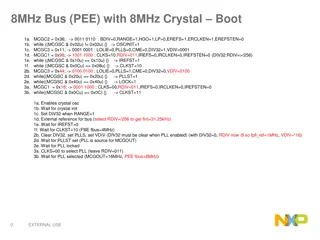
Putting it all together wire clk,locked; Pll myPll(.inclk0(CLOCK_50),.c0(clk), .locked(locked)); wire reset=(!locked)|!KEY[0]; always @(posedge clk or posedge reset) if(reset) begin some_var<=some_var_init_val; end else begin your normal code, e.g. some_var <= ; end 16 Jan 2014 Lecture 4: Clocks and PLLs 11
Resulting design: 16 Jan 2014 Lecture 4: Clocks and PLLs 12
Do this for all reg variables? No, just the ones that matter Some FFs need no initialization Can leave those uninitialized and/or assign w/o checking PLL lock But easier to just init and lock-check everything If something needed initialization and/or lock-check but you didn t do it, the resulting bug is very hard to find Heisenbug sometimes it manifests, sometimes not Whether a Heisenbug-infested design works or not depends on: Value that FF starts with How many cycles the PLL needs to lock Manufacturing variations (exact timing of gates on your board) Temperature (changes speed of gates) And many other things 16 Jan 2014 Lecture 4: Clocks and PLLs 13
What if I do this always @(posedge clk or negedge lock) if(!lock) begin some_var<=some_var_init_val; end else begin your normal code, e.g. some_var <= ; end Same behavior but This puts initialization logic on every path! With or negedge lock , uses SET/CLR inputs on FFs 16 Jan 2014 Lecture 4: Clocks and PLLs 14
Note the difference! 16 Jan 2014 Lecture 4: Clocks and PLLs 15
Extra Background on Initialization and Glitches 16
Our On/Off Switch Again module Lectures(LEDG, KEY); output [0:0] LEDG; input [3:0] KEY; wire flip = ! KEY[3]; reg state; always @(posedge flip) state <= !state; assign LEDG[0]=state; endmodule Is LEDG[0] initially on or off? 16 Jan 2014 Lecture 4: Clocks and PLLs 17
Initialization module Lectures(LEDG, KEY); output [0:0] LEDG; input [3:0] KEY; wire flip = ! KEY[3]; reg state=0; always @(posedge flip) state <= !state; assign LEDG[0]=state; endmodule The initial value of the state flip-flop should be zero 16 Jan 2014 Lecture 4: Clocks and PLLs 18
Initialization module Lectures(LEDG, KEY); output [0:0] LEDG; input [3:0] KEY; wire flip = ! KEY[3]; reg state; initial begin state=0; end always @(posedge flip) state <= !state; assign LEDG[0]=state; endmodule Same as previous slide, but allows for more complex initialization Usually you put the initial statement where the always block for that FF is 16 Jan 2014 Lecture 4: Clocks and PLLs 19
Initialization and Reset module Lectures(LEDG, KEY); output [0:0] LEDG; input [3:0] KEY; wire flip = ! KEY[3]; wire reset=!KEY[2]; reg state; initial begin state=0; end always @(posedge flip or posedge reset) if(reset) state<=0; else state <= !state; assign LEDG[0]=state; endmodule Initialize the state when the board is turned on or programmed! Allows us to initialize the state using a reset signal! 16 Jan 2014 Lecture 4: Clocks and PLLs 20
Glitches Signals can briefly have wrong values Due to logic delays and how they play together Example: 4-bit adder Inputs were 0000 and 0000, output is 0000 Inputs change to 0001 and 1111, output stays 0000 Actually, output changes briefly, then becomes 0000 Why? Let s just look at the MSB part of the adder Takes two inputs and carry, produces output bit Problem: takes time for carry to arrive, meanwhile MSB output is 1 16 Jan 2014 Lecture 4: Clocks and PLLs 21
Glitch demo reg [3:0] cntr1,cntr2; initial begin cntr1 = 4'h0; cntr2 = 4'h0; end always @(posedge mykey[3]) begin cntr1 <= cntr1+4'h1; cntr2 <= cntr2-4'h1; end wire [3:0] sum = cntr1 + cntr2; // Should always be 0000 wire sumnz = (sum != 0); // Should always be 0 Two counters that start at 0 and count in opposite directions Counts how many times sumnz became 1 reg [9:0] nzCnt; initial nzCnt = 0; always @(posedge sumnz) nzCnt <= nzCnt + 9'd1; assign LEDG = {sumnz,3'b0,sum}; assign LEDR=nzCnt; 16 Jan 2014 Lecture 4: Clocks and PLLs 22