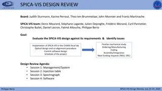
Co-alignment and Co-phasing procedure for SPICA VIS and CHARA
In the co-alignment procedure, the use of the STS Beam Combination Laboratory, visible tables, and adjustment modules like angular, lateral, and OPD are essential for aligning and phasing SPICA VIS with CHARA. The SPICA adjustment modules provide specifications for accuracy in various adjustment aspects like image adjustment, feeding optics, pupil adjustment, and more. The system ensures precise alignment and control for optimal performance during the co-alignment process. Detailed reviews and specifications are provided for each module to guide the co-alignment procedure effectively.

Download Presentation

Please find below an Image/Link to download the presentation.
The content on the website is provided AS IS for your information and personal use only. It may not be sold, licensed, or shared on other websites without obtaining consent from the author.If you encounter any issues during the download, it is possible that the publisher has removed the file from their server.
You are allowed to download the files provided on this website for personal or commercial use, subject to the condition that they are used lawfully. All files are the property of their respective owners.
The content on the website is provided AS IS for your information and personal use only. It may not be sold, licensed, or shared on other websites without obtaining consent from the author.
E N D
Presentation Transcript
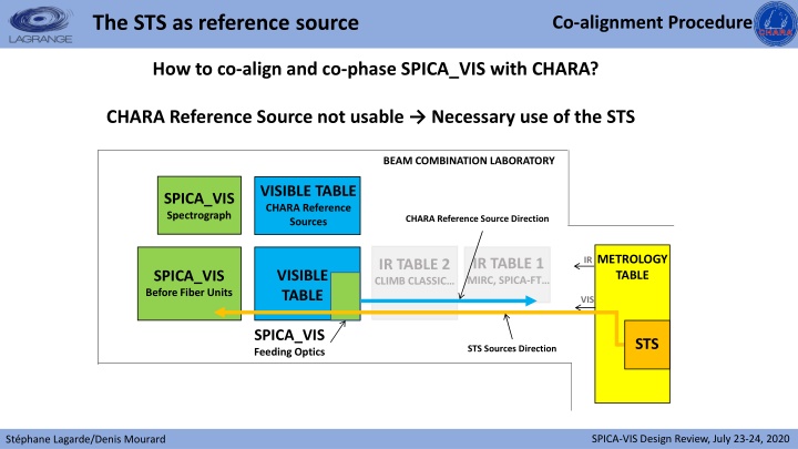
The STS as reference source Co-alignment Procedure How to co-align and co-phase SPICA_VIS with CHARA? CHARA Reference Source not usable Necessary use of the STS BEAM COMBINATION LABORATORY VISIBLE TABLE CHARA Reference Sources SPICA_VIS Spectrograph CHARA Reference Source Direction METROLOGY TABLE IR IR TABLE 1 MIRC, SPICA-FT IR TABLE 2 CLIMB CLASSIC VISIBLE TABLE SPICA_VIS Before Fiber Units VIS SPICA_VIS Feeding Optics STS STS Sources Direction SPICA-VIS Design Review, July 23-24, 2020 St phane Lagarde/Denis Mourard
The SPICA adjustment modules Co-alignment Procedure ANGULAR ADJUSTEMENT MODULES Specification: Accuracy < 10as BCS-BCD SFO-IMG (Image Adjustment) BCS-PIS BCS-FOM BCS-BCC CHARA VISIBLE TABLE SFU-SDL (SPICA Delay Lines) ADC (Atmospheric Dispersion Compensator) SHU PDC (Polarizat ion Delay Compens ator) SFO-FOP (Feeding Optics) BFO-RFL BAS-COL BAS-FOC BFO-BSP BAS-PUP (Pupil Adjustment) BAS-TTT (Tip/Tilt Tracker) SPICA-VIS Design Review, July 23-24, 2020 St phane Lagarde/Denis Mourard
The SPICA adjustment modules Co-alignment Procedure LATERAL ADJUSTEMENT MODULES Specification: Accuracy < 1mm BCS-BCD BCS-PIS SFO-IMG BCS-FOM BCS-BCC (Image Adjustment) CHARA VISIBLE TABLE SFU-SDL (SPICA Delay Lines) ADC (Atmospheric Dispersion Compensator) SHU PDC (Polarizat ion Delay Compens ator) SFO-FOP (Feeding Optics) BFO-RFL BAS-COL BAS-FOC BFO-BSP BAS-PUP (Pupil Adjustment) BAS-TTT (Tip/Tilt Tracker) SPICA-VIS Design Review, July 23-24, 2020 St phane Lagarde/Denis Mourard
The SPICA adjustment modules Co-alignment Procedure OPD ADJUSTEMENT MODULES Specification: Accuracy < 7 m BCS-BCD BCS-PIS SFO-IMG BCS-FOM BCS-BCC (Image Adjustment) CHARA VISIBLE TABLE SFU-SDL (SPICA Delay Lines) ADC (Atmospheric Dispersion Compensator) SHU PDC (Polarizat ion Delay Compens ator) SFO-FOP (Feeding Optics) BFO-RFL BAS-COL BAS-FOC BFO-BSP BAS-PUP (Pupil Adjustment) BAS-TTT (Tip/Tilt Tracker) SPICA-VIS Design Review, July 23-24, 2020 St phane Lagarde/Denis Mourard
The SPICA adjustment modules Co-alignment Procedure THE SPICA BEAM CONTROL SYSTEM Specification: Sampling Image: 3pixels per /D Pupil: 40pixels BCS BCS-BCD (Beam Control System) BCS-PIS SFO-IMG BCS-FOM BCS-BCC (Image Adjustment) CHARA VISIBLE TABLE SFU-SDL (SPICA Delay Lines) ADC (Atmospheric Dispersion Compensator) SHU PDC (Polarizat ion Delay Compens ator) SFO-FOP (Feeding Optics) BFO-RFL BAS-COL BAS-FOC BFO-BSP BAS-PUP (Pupil Adjustment) BAS-TTT (Tip/Tilt Tracker) SPICA-VIS Design Review, July 23-24, 2020 St phane Lagarde/Denis Mourard
The co-alignment procedure Co-alignment Procedure 1 Find the reference axis of SPICA b) Determination of the image and pupil reference positions CHARA (STS_VIS) BCS-PIS BCS-BCD BCS-BCC SFO-IMG BCS-FOM SFO-FOP SFU BFO-BSP FBI BAS-TTT SPICA AXIS BAS-PUP BFO-RFL a) Back Illumination of the fiber SPICA-VIS Design Review, July 23-24, 2020 St phane Lagarde/Denis Mourard
The co-alignment procedure Co-alignment Procedure 2 Co-align SPICA and CHARA a) Illumination of SPICA by the STS source b) Comparison between image and pupil positions and the references CHARA (STS_VIS) BCS-PIS BCS-BCD BCS-BCC SFO-IMG BCS-FOM SFO-FOP SFU BFO-BSP FBI BAS-TTT SPICA AXIS CHARA AXIS BAS-PUP BFO-RFL c) Adjustment of the beam the angular and lateral SPICA-VIS Design Review, July 23-24, 2020 St phane Lagarde/Denis Mourard
a) Co-phasing between STS and IR instruments CHARA (STS) DICHROICS VIS/IR IR INSTRUMENTS: MIRC OU SPICA_FT c) Adjustment of the SPICA internal Delay Lines SFO-IMG SFU-SDL SFO-FOP SFU SDT CAO BFO-BSP DIS BAS-TTT BAS-PUP b) Determination of the OPD difference between SPICA and IR instruments


 Co-phasing between STS and IR instruments")
 Co-phasing between STS and IR instruments")