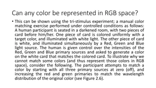
Color Specification in WebGL: Vertex and Fragment Shaders
Colors in WebGL are specified for each vertex and fragment using shaders. By passing specific colors for each vertex using color data arrays, we can control the color rendering process. This involves setting colors at the vertex level and passing them to the shaders for fragment processing.

Uploaded on Feb 26, 2025 | 1 Views
Download Presentation

Please find below an Image/Link to download the presentation.
The content on the website is provided AS IS for your information and personal use only. It may not be sold, licensed, or shared on other websites without obtaining consent from the author.If you encounter any issues during the download, it is possible that the publisher has removed the file from their server.
You are allowed to download the files provided on this website for personal or commercial use, subject to the condition that they are used lawfully. All files are the property of their respective owners.
The content on the website is provided AS IS for your information and personal use only. It may not be sold, licensed, or shared on other websites without obtaining consent from the author.
E N D
Presentation Transcript
Graphics CSCI 343 Lecture 4: Color, Viewing WebGL Color Specification Colors are set for each vertex and fragment by the fragment shader. We can pass specific colors for each vertex to the shaders using a color data array. We can either pass one array containing both vertex location and vertex color, Or we can create two separate arrays, one for color and one for position. 1
Example: the color_square( ) function var points[ ]; var colors[ ]; ... function color_square( ) { var vertices = [ vec3(-1.0, -1.0, 0.0 ), vec3(-1.0, 1.0, 0.0 ), vec3( 1.0, 1.0, 0.0 ), vec3( 1.0, -1.0, 0.0 ]; // add colors and vertices for one triangle var baseColors = [vec3(1.0, 0.0, 0.0), vec3(0.0, 1.0, 0.0),]; triangle(vertices[0], vertices[1], vertices[2], baseColors[0]); triangle(vertices[0], vertices[2], vertices[3], baseColors[1]); } //end color square function triangle(a, b, c, color) { colors.push( color ); points.push( a ); colors.push( color ); points.push( b ); colors.push( color ); points.push( c ); } //end triangle //first vertex //second vertex //third vertex
In the init( ) function: var cBuffer = gl.createBuffer(); gl.bindBuffer( gl.ARRAY_BUFFER, cBuffer ); gl.bufferData( gl.ARRAY_BUFFER, flatten(colors), gl.STATIC_DRAW ); var vColor = gl.getAttribLocation( program, "vColor" ); gl.vertexAttribPointer( vColor, 3, gl.FLOAT, false, 0, 0 ); gl.enableVertexAttribArray( vColor ); Note: You still need to have the code for vPosition. The code for the two buffers is very similar. 3
Assigning Color in the Shaders We use the keyword, attribute, to indicate variables whose values are input to the vertex shader from the graphics program. We use the keyword, varying, to indicate variables that are output from the vertex shader and passed to the fragment shader. 4
The new shaders <script id="vertex-shader" type="x-shader/x-vertex"> attribute vec3 vPosition; attribute vec3 vColor; varying vec4 color; void main() { gl_Position = vec4(vPosition, 1.0); color = vec4(vColor, 1.0); //output to fragment shader } </script> <script id="fragment-shader" type="x-shader/x-fragment"> precision mediump float; varying vec4 color; //input from vertex shader void main() { gl_FragColor = color; } </script> //passed to vertex shader //passed to vertex shader //output to the fragment shader
The Clipping Volume The region of the scene that's imaged is the clipping volume. (Or the clipping rectangle for 2D images). far top right left near bottom Regions outside the clipping volume are not rendered. 6
WebGL default The default clipping volume for WebGL is a 2-unit cube. Each dimension (x, y and z) ranges from -1 to 1. far plane at z = -1 (-1, 1, 1) (1, 1, 1) (-1, -1, 1) (1, -1, 1) The camera image plane is located at z = 0. The camera points along the negative z axis. For orthographic projection, items behind the camera are also imaged. WebGL uses orthographic projection as the default. 7
Orthographic projection Orthographic projection sets all Z values to zero. Point P = (X, Y, Z), will project to image point p = (x, y) where x = X and y = Y Y P = (Xp, Yp, Zp) Yp Z 8
View Ports Clipping window is defined in world coordinates. WebGL renders the image in screen coordinates. WebGL must translate the image from world coordinates to the screen pixel coordinates. The drawing region on the screen is called the viewport. 9
Defining a viewport gl.viewport(x, y, width, height); w h (x, y) Lower lefthand corner 10
Mapping from world to screen Want entire image from the clipping region to be mapped onto the entire viewport. Therefore, you need to make the height/width (aspect ratio) the same for both (or you will get a distorted image). wv wc Demo with triangle1.js hv hc Clipping ViewPort 11
Calculating the mapping Points on the left border of the clipping window, map to points on the left border of the viewPort. Points on the right border of the clipping window, map to points on the right border of the viewPort. Points 1/3 of the width from the left in the clipping window, map to points 1/3 of the width from the left in the viewPort. 1/3wv 1/3wc 12
Animation To animate an object in WebGL, the program changes something about the object (e.g. its position) and then redraws it. Computing a new set of positions for every vertex in our scene, and then resending all the position information to the GPU, is inefficient. Instead, we send the vertex positions once, and have a small number of variables that indicate how the position is changing that we send to the GPU. The new positions are calculated by the vertex shaders. 13
Example: Rotating Square (-sin( ), cos( )) The vertices of a square inscribed in the unit circle can be given in terms of the sin and cos of the angle of rotation of the square. (-cos( ), -sin( )) (cos( ), sin( )) (sin( ), -cos( )) To rotate the square, we start with initial values for each vertex and theta = 0, which are sent to the vertex shader. We then increment theta and send it to the vertex shader, which re-computes the vertex positions. 14
Drawing the initial square var vertices = [ vec2(0, 1), vec2(1, 0), vec2(-1, 0), vec2(0, -1)]; ... //Bind the initial vertex positions var bufferId = gl.createBuffer(); gl.bindBuffer( gl.ARRAY_BUFFER, bufferId ); gl.bufferData( gl.ARRAY_BUFFER, flatten(vertices), gl.STATIC_DRAW ); ... //Get the location of the uniform variable, theta, from the // vertex shader program //A uniform variable remains the same for all vertices in an object. thetaLoc = gl.getUniformLocation( program, "theta" ); render(); 15
Calculate the vertex positions in the vertex shader attribute vec4 vPosition; uniform float theta; void main() { float s = sin( theta ); float c = cos( theta ); gl_Position.x = -s * vPosition.x + c * vPosition.y; gl_Position.y = s * vPosition.y + c * vPosition.x; gl_Position.z = 0.0; gl_Position.w = 1.0; } 16
Double Buffering Problem: When we re-draw the object in a new position, the new drawing might not be synchronized with the frame rate of the monitor. Solution: Use double buffering. Draw into one buffer while displaying the other, then swap the two. This way we can guarantee that a scene is displayed only after the drawing is finished. 17
Double Buffering WebGL automatically uses double-buffering. The front buffer is the one displayed. The back buffer is the one into which we draw. To request the browser to display the new version of the square use: requestAnimFrame(render); This will refresh the display with the new rendering. It then calls render (recursively). 18
A new render function function render() { gl.clear( gl.COLOR_BUFFER_BIT ); theta += 0.1; gl.uniform1f( thetaLoc, theta ); gl.drawArrays( gl.TRIANGLE_STRIP, 0, 4 ); window.requestAnimFrame(render); } Note: gl.uniform1f(thetaLoc, theta); sends the new theta to the vertex shader. The 1f in the function name means we are sending 1 floating point value. Both thetaLoc and theta were declared as global variables. 19
Input and output devices Input: Keyboard, mouse, light pen, track ball, joystick Information sent to the computer depends on the device: Keyboard: ASCII characters Mouse: Move, position, button click (up or down) Output: Printer, monitor 20
Program requests for input 1) Request Mode Program requests information from the device and waits for a reply. Device collects information into a buffer until a trigger is hit. Then it sends the information to the computer Example: scanf( ) in C is used to read input from the keyboard. The program waits for the user to enter information and hit <return> (<enter>). 2) Sample Mode Program calls a function that measures and returns a device value (e.g. the mouse position). No trigger is needed. This mode is immediate. Problem: program controlled, not user controlled. 21
Event driven programming Event mode: Every time a device is triggered, it generates an event. Device identifier and measure are stored in the event queue. Example: Mouse click-- Event: Button down Device: left-button Measure: Mouse current position The program examines the events in the queue and responds to them (or not). (The program only responds if it has instructions for handling that particular event). 22
Callback functions The program handles specific events using callback functions. (Also known as Event handlers, or Event Listeners) Program specifies which function should be called for a given event. When a particular event occurs, the specified function is called to handle the event. We will create callback functions for menus, mouse clicks, etc. 23
The client-server model The workstation is the server. It provides input through the keyboard and mouse. It provides output through the monitor (raster display). The program is the client. It requests information from the input devices and sends information to the output devices. Our client and server are the same machine, but they could work over a network. Client program CRT Network server keyboard 24

 function")
 function:")