COMPARATORS AND CONVERTERS
Comparators in electronics compare two signal voltages, determining output based on input differences. Learn about basic comparators, SAR-ADC functioning, and ECG signal properties in electronic circuits.
Download Presentation

Please find below an Image/Link to download the presentation.
The content on the website is provided AS IS for your information and personal use only. It may not be sold, licensed, or shared on other websites without obtaining consent from the author.If you encounter any issues during the download, it is possible that the publisher has removed the file from their server.
You are allowed to download the files provided on this website for personal or commercial use, subject to the condition that they are used lawfully. All files are the property of their respective owners.
The content on the website is provided AS IS for your information and personal use only. It may not be sold, licensed, or shared on other websites without obtaining consent from the author.
E N D
Presentation Transcript
COMPARATORS AND COMPARATORS AND CONVERTERS CONVERTERS
COMPARATORS COMPARATORS Comparator, as its name implies, compares two signals voltages, from which one is the signal of interest and the other one is called reference voltage. It is an open loop op-amp, with two inputs. As the circuit is open-loop, the output always remains in saturation. But the polarity of saturation is decided by the difference of two inputs.
BASIC COMPARATOR BASIC COMPARATOR
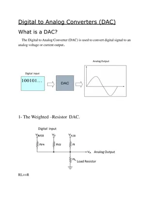
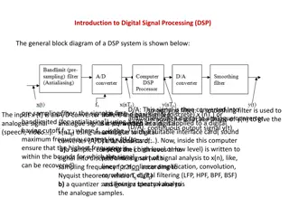
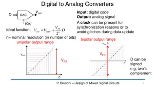
ADC The main part of the circuit is the 8-bit SAR, whose output is given to an 8-bit D/A converter. The analog output Vaof the D/A converter is then compared to an analog signal Vinby the comparator. The output of the comparator is a serial data input to the SAR. Till the digital output (8 bits) of the SAR is equivalent to the analog input Vin,the SAR adjusts itself. The 8-bit latch at the end of conversation holds onto the resultant digital data output.
At the start of a conversion cycle, the SAR is reset by making the start signal (S) high. The MSB of the SAR (Q7) is set as soon as the first transition from LOW to HIGH is introduced. The output is given to the D/A converter which produces an analog equivalent of the MSB and is compared with the analog input Vin. If comparator output is LOW, D/A output will be greater than Vinand the MSB will be cleared If comparator output is HIGH, D/A output will be less than Vinand the MSB will be set to the next position (Q7 to Q6) by the SAR. According to the comparator output, the SAR will either keep or reset the Q6 bit. This process goes on until all the bits are tried. After Q0 is tried, the SAR makes the conversion complete (CC) signal HIGH to show that the parallel output lines contain valid data. The CC signal in turn enables the latch, and digital data appear at the output of the latch. As the SAR determines each bit, digital data is also available serially. As shown in the figure above, the CC signal is connected to the start conversion input in order to convert the cycle continuously. by the SAR.
ECG signal Properties of the electric signals on the skin: AC signal with bandwidth of 0.05 to to 100 Hz, sometimes up to 1 kHz About 1 mV peak-to-peak amplitude External noise at higher frequencies 50/60 Hz interference Common-mode voltages (common to all electrodes)
ECG SIGNAL ECG SIGNAL The common-mode voltage is comprised of two parts: 1) 50- or 60-Hz interferences 2) DC electrode offset potential Other noise or higher frequencies within the biophysical bandwidth come from: Movement artifacts that change the skin-electrode interface Muscle contraction or electromyographic spikes Respiration Electromagnetic interferences Noise from other electronic devices that couple into the input
ECG amplifier ECG amplifier The technic usually employed to amplify bioelectric signals is the use of a differential amplifier. A differential amplifier is an amplifier which amplifies difference between two inputs. Common mode gain of these amplifiers are nearly zero which makes them less susceptible to noise. (due to high CMRR) High CMRR of op-amp amplifiers, rejects following two common mode signals: 50 Hz mains interference DC electrode offset potential Some noise can be cancelled with a high-input-impedance instrumentation amplifier (INA) removes the AC line noise common to both inputs amplifies the remaining unequal signals present on the inputs
CARDIAC MONITORS CARDIAC MONITORS Patient monitoring systems vary greatly in size and configuration depending on manufacturer as well as user, some basic elements are common in all. Skin electrodes to pick up ECG Amplifier similar to ECG amplifier discussed before CRT bedside with small screen, which is specific to the patient . And another which is with large display have the ECG of all the patients in ward, at nurse station. A rate meter used to indicate average heart rate, might have audible or flashing light for indication of each heart beat An alarm system actuated by rate meter, to alert nurse or observer
In addition to this, a direct write out device to obtain, a permanent record of ECG seen on CRT A memory tape loop to record and playback the ECG for 15 to 60 seconds prior to alarm Additional alarm triggered by ECG parameters other than heart rate, ex. Widening of QRS complex Electrical circuits to indicate that an electrode has become disconnected or the mechanical failure has occurred somewhere else in monitoring system


