Comparison of Dynamic and Fixed CSD Start Index Assignment
In September 2024, a comparison study was conducted between dynamic and fixed CSD start index assignment schemes for DRU transmission. The study highlighted differences in power measurement accuracy, performance, and complexity. Various discussions emphasized the impact of time synchronization errors on each scheme's effectiveness.

Download Presentation

Please find below an Image/Link to download the presentation.
The content on the website is provided AS IS for your information and personal use only. It may not be sold, licensed, or shared on other websites without obtaining consent from the author.If you encounter any issues during the download, it is possible that the publisher has removed the file from their server.
You are allowed to download the files provided on this website for personal or commercial use, subject to the condition that they are used lawfully. All files are the property of their respective owners.
The content on the website is provided AS IS for your information and personal use only. It may not be sold, licensed, or shared on other websites without obtaining consent from the author.
E N D
Presentation Transcript
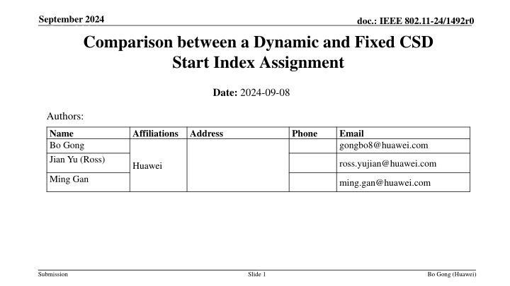
September 2024 doc.: IEEE 802.11-24/1492r0 July 2024 Comparison between a Dynamic and Fixed CSD Start Index Assignment Date: 2024-09-08 Authors: Name Bo Gong Jian Yu (Ross) Affiliations Address Phone Email gongbo8@huawei.com ross.yujian@huawei.com Huawei Ming Gan ming.gan@huawei.com Submission Slide 1 Bo Gong (Huawei)
September 2024 doc.: IEEE 802.11-24/1492r0 July 2024 Background For DRU transmission, two schemes are proposed for a CSD start index assignment. In ref [1], it is suggested that the CSD start index for each user is allocated by an AP and indicated in the User Info field of the trigger frame, referred to as the dynamic scheme. In ref [2], it is suggested that the CSD start index for each user is fixed to the DRU index, referred to as the fixed scheme. Submission Slide 2 Bo Gong (Huawei)
September 2024 doc.: IEEE 802.11-24/1492r0 July 2024 Recap of the Discussion In terms of performance, ref [1] points out that the dynamic scheme provides more accurate power measurement than the fixed scheme and the power gap range gain is up to 5dB. Whilst ref [2] illustrates that the power measurement accuracy of the dynamic and fixed schemes are almost the same. For the different opinions, the reason is that ref [1] assumes ideal time synchronization whilst ref [2] assumes a random time synchronization error in the range of [-0.4, 0.4]us for each STA. Note that ref [1] has considered random phase synchronization error, instead of ideal phase synchronization illustrated in ref [2]. In terms of complexity, ref [1] points out that for the fixed scheme, it requires a totally new implementation of the look-up tables of each DBW. Ref [2] points out that the dynamic scheme makes an AP scheduler more complex taking into consideration a CSD assignment. Submission Slide 3 Bo Gong (Huawei)
September 2024 doc.: IEEE 802.11-24/1492r0 July 2024 Analysis of the Time Synchronization Error 1. Allowed Time Synchronization Error of TB PPDU in Spec In the section of the 11ax/be Spec for Transmit requirement for PPDUs sent in response to a triggering frame , there exists the description that A STA that transmits TB PPDU in response to a triggering PPDU shall ensure that the transmission start time of the TB PPDU is within 0.4?? + 16??from the end of the last OFDM symbol of the triggering PPDU . This sentence means that as soon as the end of the last OFDM symbol of the triggering PPDU arrives, the TB PPDU shall be transmitted in 0.4?? + 16??. For the spec, the reason for selecting 0.4?? as the time synchronization error limitation is that 0.4?? guarantees negligible impact on the PER performance. The simulation results can be found in ref [3]. Submission Slide 4 Bo Gong (Huawei)
September 2024 doc.: IEEE 802.11-24/1492r0 July 2024 2. Required Time Synchronization Error of TB PPDU in practical systems What we really care about is the required time synchronization error in the actual TB PPDU transmission. It is up to two factors, which are the time synchronization error of the Trigger frame and the symbol clock error of 16??. Time synchronization error of the Trigger frame BW = 80MHz Channel D SNR = 25dB Frequency offset = 6ppm The time synchronization error is investigated by simulation. The simulation parameters are listed in the framework. From the simulation results, it can be seen that the time synchronization error of the Trigger frame is smaller than 0.025?? with a probability of 75%. Submission Slide 5 Bo Gong (Huawei)
September 2024 doc.: IEEE 802.11-24/1492r0 July 2024 Symbol clock error for 16?? The symbol clock frequency offset will result in a time error. The time error of 16??will be 16?? ?? 16??, ?? 1 ??, and ?? represents the sampling interval when in which ?? is the sampling interval, which is equal to ??= there exists a symbol clock frequency offset of 6ppm. By simple calculation, the time error of 16??will be 16?? ?? ?? 16?? = 0.000096??. Considering that 0.000096?? 0.025??, it can be believed that the required time synchronization error for TB PPDU is about 0.025?? in most scenarios. It can be expected that the power gap range incurred by collision and non-optimal CSD allocation shown in ref [1] will not be affected significantly. This means that the dynamic scheme provides a more accurate power measurement than the fixed scheme and the power gap range gain is up to 5dB. Submission Slide 6 Bo Gong (Huawei)
September 2024 doc.: IEEE 802.11-24/1492r0 July 2024 Analysis of the Implementation Complexity Ref [2] points out that the dynamic scheme makes an AP scheduler more complex taking into consideration a CSD assignment. We have listed the actions of the dynamic and fixed schemes in the following table. Overall, the complexity seems not to be a big issue for both schemes. Whilst the fixed scheme requires a totally new implementation for establishing and searching the mapping table of DRU index and CSD start index. AP Non-AP STA Actions Complexity Actions Complexity Allocate CSDs for each user similar to the current CSD allocation of UL MUMIMO. Negligible complexity. Can mainly reuse the implementation of UL MUMIMO CSD allocation. Obtain CSD start index from User Info Field as UL MUMIMO. Negligible complexity. Can reuse the implementation of UL MUMIMO CSD obtaining. Dynamic scheme None None Look up table for each DBW. Negligible complexity. Totally New implementation. Fixed scheme Submission Slide 7 Bo Gong (Huawei)
September 2024 doc.: IEEE 802.11-24/1492r0 July 2024 Summary In this proposal, we compare two CSD start index allocation schemes, which are the dynamic and fixed schemes. Through simple analysis, it can be found that The dynamic scheme provides higher power measurement accuracy than the fixed scheme and the power gap range gain is up to 5dB. The dynamic scheme can reuse the implementation of a UL MUMIMO CSD allocation, whilst the fixed scheme requires a totally new implementation for establishing and searching the look-up tables of different DBWs. Thus, a dynamic scheme is more appropriate in terms of both performance and implementation. Submission Slide 8 Bo Gong (Huawei)
September 2024 doc.: IEEE 802.11-24/1492r0 July 2024 Reference [1] 11-24-1172-01-00bn-CSD indication design [2] 11-24-1188-01-00bn-Global CSD Index Assignment for DRU STF Transmission in 11bn [3] 11-14-0818-01-00ax-requirements for synchronization Submission Slide 9 Bo Gong (Huawei)
September 2024 doc.: IEEE 802.11-24/1492r0 SP 1 Do you agree to add the following text to the TGbn SFD? For DRU transmission, the CSD start index for each user is indicated in the User Info Field of the Trigger frame. Submission Slide 10 Bo Gong (Huawei)