Comparison of Fast Wire Scanner Shielding Measurements
"Explore the results of shielding measurements with and without a magnetic shield in a fast wire scanner setup. Analysis includes Bx and By field measurements, wire scan current variations, analog voltage measurements, calibration checks, and more. Discover the impact of shielding on integral fields and analog-to-field conversions." (298 characters)
Download Presentation

Please find below an Image/Link to download the presentation.
The content on the website is provided AS IS for your information and personal use only. It may not be sold, licensed, or shared on other websites without obtaining consent from the author. If you encounter any issues during the download, it is possible that the publisher has removed the file from their server.
You are allowed to download the files provided on this website for personal or commercial use, subject to the condition that they are used lawfully. All files are the property of their respective owners.
The content on the website is provided AS IS for your information and personal use only. It may not be sold, licensed, or shared on other websites without obtaining consent from the author.
E N D
Presentation Transcript
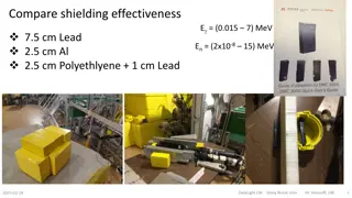
Fast Wire Scanner Shielding Measurements Results Comparison of shielding with 15 A supply with and without bottom magnetic shield. Scott Anderson 1/31/2017
Bx and By Fields with 15 A Power Supply Measurement Setup Bx and By field measurements were made with wire scanner moving in the up direction. This gives the maximum current. Bx and By analog output of the gaussmeter was measured during at 15 points at x and y = 0, from z = -14 to +14 cm (2 cm steps). The maximum field change was calculated at each step and then these steps were integrated.
Analog to Field Conversion Measurements were made on a +/- 10 G/V scale. Field (G) = (max(Volt) min(Volt))*10
Integral Fields Bx Integral Field (G-cm) By Integral Field (G-cm) Bx Integral Field w/ Bottom Shield (G-cm) By Integral Field w /Bottom Shield (G-cm) 0.57+/- 0.04 0.61 +/- 0.03 0.54 +/- 0.04 0.61 +/- 0.03
Calibration Check Used now magnet to check field calibration Hall probe measured 1.4 to 0.3 G changing field. Field measured = 1.1 G Integral Field measured = 8.5 G-cm Both measurements agree with second hall probe measurements.


