Learn about complex numbers in Cartesian and polar forms, Euler's identity, graphical representation on a complex number plane, arithmetic operations, and conversion between forms. Explore examples and concepts related to complex numbers in the context of electric circuits and engineering.
Please find below an Image/Link to download the presentation.
The content on the website is provided AS IS for your information and personal use only. It may not be sold, licensed, or shared on other websites without obtaining consent from the author. If you encounter any issues during the download, it is possible that the publisher has removed the file from their server.
You are allowed to download the files provided on this website for personal or commercial use, subject to the condition that they are used lawfully. All files are the property of their respective owners.
The content on the website is provided AS IS for your information and personal use only. It may not be sold, licensed, or shared on other websites without obtaining consent from the author.
E N D
Presentation Transcript
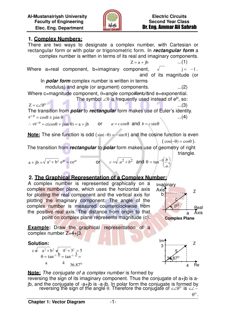
Al-Mustansiriyah University Faculty of Engineering Elec. Eng. Department Electric Circuits Second Year Class Dr. Eng. Ammar Ali Sahrab 1. Complex Numbers: There are two ways to designate a complex number, with Cartesian or rectangular form or with polar or trigonometric form. In rectangular form a complex number is written in terms of its real and imaginary components. ...(1) j = Z = a + jb 1. Where a=real component, b=imaginary component, and of its magnitude (or In polar form complex number is written in terms modulus) and angle (or argument) components. Where c=magnitude component, =angle component, and e=exponential. The symbol is frequently used instead of ej , so: Z = c O The transition from polar to rectangular form makes use of Euler s identity. e j = cos jsin ce+ j or a = ccos and b = csin = c(cos + jsin ) = a + jb ...(2) Z = cej ...(3) ...(4) Note: The sine function is odd (sin( ) = sin ) and the cosine function is even ( cos( ) = cos ). The transition from rectangular to polar form makes use of geometry of right triangle. b a a2+b2 and = tan 1 c = or a2 + b2 ej = cej a + jb = 2. The Graphical Representation of a Complex Number: A complex number is represented graphically on a complex number plane, which uses the horizontal axis for plotting the real component and the vertical axis for plotting the imaginary component. The angle of the complex number is measured counterclockwise from the positive real axis. The distance from origin to that point on complex plane represents magnitude (c). Imaginary Axis b Z c O Real Axis a Complex Plane Example: Draw the graphical representation of a complex number Z=4+j3. Im 3 Solution: c = Z a2+b2 = = tan 1 b= tan 1 3= a 42+32 = 5 5 36.87O 4 36.87O Re 4 Note: The conjugate of a complex number is formed by reversing the sign of its imaginary component. Thus the conjugate of a+jb is a- jb, and the conjugate of -a+jb is -a-jb. In polar form the conjugate is formed by reversing the sign of the angle . Therefore the conjugate of c O is c O . -1- Chapter 1: Vector Diagram
Al-Mustansiriyah University Faculty of Engineering Elec. Eng. Department Electric Circuits Second Year Class Dr. Eng. Ammar Ali Sahrab HW: Convert (Express) the following complex numbers in polar form. -6+j8, 1-j, 3-j6, -10-j10 & -2.3+j8.1 3. Arithmetic Operations on a Complex Numbers: a. Addition and Subtraction: To add or subtract complex numbers, the number must be expressed in rectangular form. if Z1 = a1 + jb1 and Z2 = a2 + jb2 then: Z1+ Z2= (a1+ a2)+ j(b1+b2) and Z1 Z2=(a1 a2)+ j(b1 b2) Example: Add and subtract the following two complex numbers Z1 = 8 + j16 and Z2 = 12 j3 . Solution: Addition, Z1 + Z2 = (8 +12) + j(16 3) = 20 + j13 Subtraction, Z2 Z1 = (12 8) + j( 3 16) = 4 j19 Note: If the complex numbers are given in polar form, they are converted to rectangular form. Example: Add and subtract the following two complex numbers Z = 10 53.13O and Z = 5 135O . 2 Solution: Addition, Z + Z = 10 53.13O + 5 135O = 6 + j8 3.535 j3.535 = 2.465 + j4.465 = 5.1 61.1O 1 2 Subtraction, O O Z1 Z2 =10 53.13 5 135 = 6+ j8+3.535+ j3.535 = 9.535+ j11.535 =14.966 50.42 1 O b. Multiplication and Division: Multiplication and division of complex numbers can be carried out with numbers in rectangular or polar form. if Z1 = a1 + jb1 and Z2 = a2 + jb2 then: Z1Z2 = c1c2 1 + 2 = (a1a2 b1b2 ) + j(a1b2 + a2b1) Z1=c1 o o =(a1a2 + b1b2 ) + j (a2b1 a1b2 ) 1 2 2 2 Z2 c2 a2+ b2 o o algebraic addition and subtraction of angles Example: Multiply and Divide the following two complex numbers Z1 = 8+ j10 and Z2 = 5 j4 . Solution: Multiplication, Z Z = (8 + j10)(5 j4) = 80 + j18 = 82 12.68O 1 2 Z1=8+j10=(8+j10)(5+j4)=0 + j82=0 +j2 =2 90O Division, Z2 5 j4 ((5 j4))(5+ j4) 41 Multiply O and Divide O the Z1 =10 53.13 and Z2 = 5 135 . following two complex numbers Example: Solution: Multiplication, Z Z = (10 53.13O)(5 135O) = 50 81.87O = 7.071 1 2 j49.498 -2- Chapter 1: Vector Diagram
Al-Mustansiriyah University Faculty of Engineering Elec. Eng. Department Electric Circuits Second Year Class Dr. Eng. Ammar Ali Sahrab O Z1=10 53.13= 2 188.13O Z 5 135O 2 Division, = 1.98 j0.283 c. Useful Identities: In working with complex numbers and quantities, the following identities are very useful. j2 = m1 or ( j)(j) = 1 j =1 j = 1 or ZZ* = a2+b2 = c2 or Z/Z* =1 2 O Z + Z* = 2a or Z Z* = j2b e j / 2= j e j nk= (a + jb)k= ckejk = ck(cosk + jsink ) HW: Multiply and Divide the following two complex numbers and find the polar and rectangular forms: Z1 = 7 + j7 and Z2 = 8 + j6 4. Phasor (Voltage) Diagram: The terms lead and lag as well as in-phase and out-of-phase were used to indicate the relationship of one waveform to the other with the generalized sinusoidal expression given as: A(t) = Am sin( t ) representing the in the time-domain form. v(t) = Vm sin( t v) and i(t) = Im sin( t i) where is the radian angular frequency (rad/sec) =2 f and f is the frequency of the wave (Hz) period for complete one wave cycle) after t seconds the displacement t=2 ft= 2 t = , T frequency domain. sinusoid v lead i =1/T (T is the lag v i angle is 0 is called so sin =sin t which Hz=Cycle/sec Note: v and i are not conditionally the same value that depend on circuit elements. Vector: It is a complex number in polar or rectangular form has an arrow head at one end which signifies partly the maximum value of the vector quantity (V or I) and partly the end of the vector rotate in angular frequency . 1. Pure Resistance "R": in this case there is no phase shift between VR and IR (i.e. v = i). i R IR IR VR - + VR -3- Chapter 1: Vector Diagram
Al-Mustansiriyah University Faculty of Engineering Elec. Eng. Department Electric Circuits Second Year Class Dr. Eng. Ammar Ali Sahrab 2. Pure Inductor "L": in this case VLleads ILby 90ophase shift (i.e. v - i = 90o). VL i L 90o IL IL + VL - 3. Pure Capacitor "C": in this case ICleads VCby 90ophase shift (i.e. i- v = 90o). i C IC IC o 90 - + VC VC Note: 1. All voltages and currents in each branch of the circuit must be found in the drawing. 2. The common electrical quantity must be taken as reference vector that should be drawn horizontally (series circuit "IT" and parallel circuit "VT"). Example: For the following electrical circuits, draw the phasor (vector) diagram. All voltages and currents must be considered. 1. The common quantity is the total current. VL V - V L C L IT R VR C VC VT VL VT IT VR VC 2. The common quantity is the total voltage. IC IT R I IL L IC C IR R VT VT IL- IC IT IL 3. The common quantity is the total voltage. IT I1 I1 I2 + VT =V IT + VR1R2 - - L VR2 + VL - VT R1 R1 I 2 VL VR2 -4- Chapter 1: Vector Diagram
Al-Mustansiriyah University Faculty of Engineering Elec. Eng. Department Electric Circuits Second Year Class Dr. Eng. Ammar Ali Sahrab 4. The common quantity is the total voltage. IC IT I T IC C VC IL R L + VR - + VL - + - VT =VC VT I L VL VR 5. The common quantity is the total voltage. IT VR2 I2 I1 I2 IT + - + VC - +R2 VR2 VR1 - C VT R1 VC VT=VR1 I1 6. The common quantity is the total voltage. IT VR IT I1 I2 + + VC2 - + I 1 C VC1R 1 -R VT I2 VC2 -C2 V VT=VC1 7. The common quantity is the total voltage. IT VR VC IL L VL IC R C + VR + VC - IC + - VT - V =V T L IT IL 8. The common quantity is the total voltage. IT I1 I1 I2 + VR2 - + VL - VT =V IT + VR1R2 - VT R1 R1 I L 2 VL VR2 9. The common quantity is the total voltage. IC IT I T IC C IL R L + VR - + VL - VT =VC + VC - VT I L VL VR -5- Chapter 1: Vector Diagram
Al-Mustansiriyah University Faculty of Engineering Elec. Eng. Department Electric Circuits Second Year Class Dr. Eng. Ammar Ali Sahrab 10. The common quantity is the total voltage. IT I1 L1 V I2 + VR - + VL2 - VT=VL1 +R -L1 I2 VT I1 VR L2 VL2 IT 11. The common quantity is the total voltage. IT I2 I3 I2 I1 VT=VR1= VL=VR2 I4 L I3 R1 + - + VL R2 VR2 - + VR1 - VT I 1 I 4 IT 12. The common quantity is the total voltage. At resonance VL=VC and VT=0. a. If VL> VC I1 VL VT=V I =VL-V VC IT I2 C T R I2 I1 R VR + VL - + VC - + L - b. If VC> VL VT IT I2 C VT=VR VC I1 VL =VC-VL 13. The common quantity is the total voltage. At resonance IT is in phase with VT (zero angle between them). VR1 VR1 VC VC I1 IT I1 IT I2 I1 + VR2 - + VL - + VR1 + VC - VT VT R2 R1 IT - I2 VT I2 VL VL L C VR2 VR2 b. Capacitive a. Inductive 14. The common quantity is the total current. At resonance IC = IL and IT = 0. a. If IC> IL VT VL= VC IT R +VR -IC IC IL L IL VR + IT=IL-IC + VC - VL VT C b. If IL> IC IL - VR IC IT=IC-IL VC= VT VL -6- Chapter 1: Vector Diagram
Al-Mustansiriyah University Faculty of Engineering Elec. Eng. Department Electric Circuits Second Year Class Dr. Eng. Ammar Ali Sahrab 15. The common quantity is the total current. At resonance VT and IT are in phase. 16. The common quantity is the total current. 17. The common quantity is the total current. C1 IT IC IL +VC1- + VR1 L + VC2 - + + VP - R2 R1 - - VT VR2 + VL - C 2 Capacitive Inductive HW: Draw the full detailed phasor diagram for the following circuit. LS ITRS IL IC RL RC VT C L -7- Chapter 1: Vector Diagram