Comprehensive Guide to Flow-Control Valves in Hydraulic Systems
Flow-control valves play a crucial role in regulating fluid flow in hydraulic circuits, ensuring proper velocity and speed control for various actuators. This article covers the functions, classification, and importance of flow-control valves, highlighting their role in maintaining system stability and preventing damage due to oversupply of fluid. The discussion includes insights into non-pressure-compensated valves and how they address the challenges of varying workloads and pressures in hydraulic applications.

Download Presentation

Please find below an Image/Link to download the presentation.
The content on the website is provided AS IS for your information and personal use only. It may not be sold, licensed, or shared on other websites without obtaining consent from the author. If you encounter any issues during the download, it is possible that the publisher has removed the file from their server.
You are allowed to download the files provided on this website for personal or commercial use, subject to the condition that they are used lawfully. All files are the property of their respective owners.
The content on the website is provided AS IS for your information and personal use only. It may not be sold, licensed, or shared on other websites without obtaining consent from the author.
E N D
Presentation Transcript
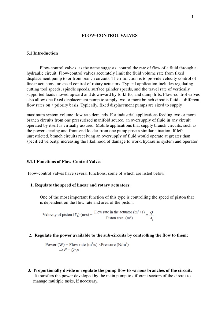
1 FLOW-CONTROL VALVES 5.1 Introduction Flow-control valves, as the name suggests, control the rate of flow of a fluid through a hydraulic circuit. Flow-control valves accurately limit the fluid volume rate from fixed displacement pump to or from branch circuits. Their function is to provide velocity control of linear actuators, or speed control of rotary actuators. Typical application includes regulating cutting tool speeds, spindle speeds, surface grinder speeds, and the travel rate of vertically supported loads moved upward and downward by forklifts, and dump lifts. Flow-control valves also allow one fixed displacement pump to supply two or more branch circuits fluid at different flow rates on a priority basis. Typically, fixed displacement pumps are sized to supply maximum system volume flow rate demands. For industrial applications feeding two or more branch circuits from one pressurized manifold source, an oversupply of fluid in any circuit operated by itself is virtually assured. Mobile applications that supply branch circuits, such as the power steering and front-end loader from one pump pose a similar situation. If left unrestricted, branch circuits receiving an oversupply of fluid would operate at greater than specified velocity, increasing the likelihood of damage to work, hydraulic system and operator. 5.1.1 Functions of Flow-Control Valves Flow-control valves have several functions, some of which are listed below: 1. Regulate the speed of linear and rotary actuators: One of the most important function of this type is controlling the speed of piston that is dependent on the flow rate and area of the piston: 2. Regulate the power available to the sub-circuits by controlling the flow to them: 3. Proportionally divide or regulate the pump flow to various branches of the circuit: It transfers the power developed by the main pump to different sectors of the circuit to manage multiple tasks, if necessary.
2 A partially closed orifice or flow-control valve in a hydraulic pressure line causes resistance to pump flow. This resistance raises the pressure upstream of the orifice to the level of the relief- valve setting and any excess pump flow passes via the relief valve to the tank (fig. 5.1). Figure 5.1: simple restrictor-type flow-control valves. Thus, the law that governs the flow rate across a given orifice can be approximately defined as This implies that any variation in the pressure upstream or downstream of the orifice changes the pressure differential p and thus the flow rate through the orifice (Fig. 5.2).
3 Figure 5.2: Variation of flow rate with pressure drop 5.1.2 Classification of Flow-Control Valves Flow-control valves can be classified as follows: 1. Non-pressure compensated. 2. Pressure compensated. 5.1.2.1 Non-Pressure-Compensated Valves Non-pressure-compensated flow-control valves are used when the system pressure is relatively constant and motoring speeds are not too critical. The operating principle behind these valves is that the flow through an orifice remains constant if the pressure drop across it remains the same. In other words, the rate of flow through an orifice depends on the pressure drop across it. The disadvantage of these valves is discussed below. The inlet pressure is the pressure from the pump that remains constant. Therefore, the variation in pressure occurs at the outlet that is defined by the work load. This implies that the flow rate depends on the work load. Hence, the speed of the piston cannot be defined accurately using non-pressure-compensated flow-control valves when the working load varies. This is an extremely important problem to be addressed in hydraulic circuits where the load and pressure vary constantly.
4 Figure 5.3: Non-pressure-compensated needle-type flow-control valve. (a) Fully closed; (b) partially opened; (c) fully opened. 5.1.2.2 Pressure-Compensated Valves Pressure-compensated flow-control valves overcome the difficulty caused by non-pressure- compensated valves by changing the size of the orifice in relation to the changes in the system pressure. This is accomplished through a spring-loaded compensator spool that reduces the size of the orifice when pressure drop increases. Once the valve is set, the pressure compensator acts to keep the pressure drop nearly constant. It works on a kind of feedback mechanism from the outlet pressure. This keeps the flow through the orifice nearly constant. Schematic diagram of a pressure compensated flow-control valve is shown in Fig. 5.4. A pressure-compensated flow-control valve consists of a main spool and a compensator spool. The adjustment knob controls the main spool s position, which controls the orifice size at the outlet. The upstream pressure is delivered to the valve by the pilot. The compensator spring biases the spool so that it tends toward the fully open position. If the pressure drop across the valve increases, that is, the upstream pressure increases relative to the downstream pressure, the compensator spool moves to the right against the force of the spring. This reduces the flow that in turn reduces the pressure drop and tries to attain an equilibrium position as far as the flow is concerned. (a)
5 (b) (c) Figure 5.4 : Pressure-Compensated Valve (a) no load (b) partially loaded (c) full loaded 5.2 Speed-Controlling Circuits In hydraulic operations, it is necessary to control the speed of the actuator so as to control the force, power, timing and other factors of the operation. Actuator speed control is achieved by controlling the rate of flow into or out of the cylinder. Speed control by controlling the rate of flow into the cylinder is called meter-in control. Speed control by controlling the rate of flow out of the cylinder is called meter-out control. 5.2.1 Meter-In Circuit Figure 5.5 shows a meter-in circuit with control of extend stroke. The inlet flow into the cylinder is controlled using a flow-control valve. In the return stroke, however, the fluid can bypass the needle valve and flow through the check valve and hence the return speed is not controlled. This implies that the extending speed of the cylinder is controlled whereas the retracing speed is not.
6 Figure 5.5: Meter-in circuit 5.2.2 Meter-Out Circuit Figure 5.6 shows a meter-out circuit for flow control during the extend stroke. When the cylinder extends, the flow coming from the pump into the cylinder is not controlled directly. However, the flow out of the cylinder is controlled using the flow-control valve (metering orifice). On the other hand, when the cylinder retracts, the flow passes through the check valve unopposed, bypassing the needle valve. Thus, only the speed during the extend stroke is controlled. Both the meter-in and meter-out circuits mentioned above perform the same operation (control the speed of the extending stroke of the piston), even though the processes are exactly opposite to one another.
7 Figure 5.6: Meter-Out circuit.