Comprehensive Overview of Networking Security
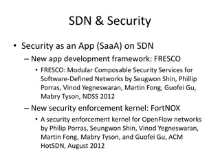
Dive into the world of networking security with a detailed exploration of local and wide-area networks, key concepts such as protocols and dumb networks, and the self-contained IP packet format. Understand how computers communicate, connect LANs, and the significance of protocols in structured communication. Explore the fundamental principles of network security and the evolution of Internet design.

Download Presentation

Please find below an Image/Link to download the presentation.
The content on the website is provided AS IS for your information and personal use only. It may not be sold, licensed, or shared on other websites without obtaining consent from the author.If you encounter any issues during the download, it is possible that the publisher has removed the file from their server.
You are allowed to download the files provided on this website for personal or commercial use, subject to the condition that they are used lawfully. All files are the property of their respective owners.
The content on the website is provided AS IS for your information and personal use only. It may not be sold, licensed, or shared on other websites without obtaining consent from the author.
E N D
Presentation Transcript
Networking Overview: Everything you need to know, in 50 minutes Network Security Prof. Haojin Zhu Adopted from David Wagner @ UC Berkeley May 8, 2019
Local-Area Networks A C point-to-point shared How does computerAsend a message to computer C? 2
Local-Area Networks: Packets From: A To: C Message: Hello world! A C Hello world! A C Hello world! 3
Wide-Area Networks A router How do we connect two LANs? C 4
Wide-Area Networks A A R A.com C.com Hello world! router How do we connect two LANs? R C C A.com C.com Hello world! A.com C.com Hello world! 5
Key Concept #1: Protocols A protocol is an agreement on how to communicate Includes syntax and semantics How a communication is specified & structured o Format, order messages are sent and received What a communication means o Actions taken when transmitting, receiving, or timer expires Example: making a comment in lecture? 1.Raise your hand. 2.Wait to be called on. 3.Or: wait for speaker to pause and vocalize 4.If unrecognized (after timeout): say excuse me 6
Key Concept #2: Dumb Network Original ( routers ) have no knowledge* of ongoing connections going through them Internet design: interior nodes Not how you picture the telephone system works Which internally tracks all of the active voice calls Instead: the postal system! Each Internet message ( packet ) self-contained * Today s Internet is full of hacks that violate this 7
Self-Contained IP Packet Format IP = Internet Protocol 8-bit 4-bit Header Length 4-bit Version 16-bit Total Length (Bytes) Type of Service (TOS) 3-bit Flags 13-bit Fragment Offset 16-bit Identification Header is like a letter envelope: contains all info needed for delivery 8-bit Time to Live (TTL) 8-bit Protocol 16-bit Header Checksum 32-bit Source IPAddress 32-bit Destination IPAddress Payload (remainder of message) . . . . .
Key Concept #2: Dumb Network Original ( routers ) have no knowledge* of ongoing connections going through them Internet design: interior nodes Not: how you picture the telephone system works Which internally tracks all of the active voice calls Instead: the postal system! Each Internet message ( packet ) self-contained Interior routers look at destination address to forward If you want smarts, build it end-to-end , not hop-by-hop Buys simplicity & robustness at the cost of shifting complexity into end systems * Today s Internet is full of hacks that violate this 9
Key Concept #3: Layering Internet design is strongly partitioned into layers Each layer relies on services provided by next layer below and provides services to layer above it Analogy: Consider structure of an application you ve written and the services each layer relies on / provides Code You Write Run-Time Library System Calls } Device Drivers Fully isolated from user programs Voltage Levels / Magnetic Domains 10
Internet Layering (Protocol Stack) Note on a point of potential confusion: these diagrams are always drawn with lower layers below higher layers Application 7 But diagrams showing the layouts of packets are often the opposite, with the lower layers at the top since their headers precede those for higher layers 4 Transport 3 (Inter)Network Link 2 1 Physical 11
Horizontal View of a Single Packet First bit transmitted Link Layer Heade r Application Data: structure depends on the application (Inter)Network Layer Header (IP) Transport Layer Header 12
Vertical View of a Single Packet Link Layer Header First bit transmitted (Inter)Network Layer Header (IP) Transport Layer Header Application Data: structure depends on the application . . . . . . . 13
Internet Layering (Protocol Stack) Application 7 4 Transport 3 (Inter)Network Link 2 1 Physical 14
Layer 1: Physical Layer Application 7 4 Encoding bits to send them over a single physical link e.g. patterns of voltage levels / photon intensities / RF modulation Transport 3 (Inter)Network Link 2 1 Physical 15
Layer 2: Link Layer Framing and transmission of a collection of bits into individual messages sent across a single subnetwork (one physical technology) Application 7 4 Transport 3 Might involve multiple physical links (e.g., modern Ethernet) (Inter)Network Link 2 1 Physical Often technology supports broadcast transmission (every node connected to subnet receives) 16
Layer 3: (Inter)Network Layer (IP) Bridges multiple subnets to provide end-to-end internet connectivity between nodes Provides global addressing Works across different link technologies } Application 7 4 Transport 3 (Inter)Network Link 2 Different for each Internet hop 1 Physical 17
Layer 4: Transport Layer End-to-end communication between processes Application Different services provided: TCP = reliable byte stream UDP = unreliable datagrams 7 4 Transport 3 (Inter)Network Link (Datagram = single packet message) 2 1 Physical 18
Layer 7: Application Layer Communication of whatever you wish Application Can use whatever transport(s) is convenient 7 4 Transport 3 Freely structured (Inter)Network Link 2 E.g.: 1 Physical Skype, SMTP (email), HTTP (Web), Halo, BitT orrent 19
Internet Layering (Protocol Stack) } Application 7 Implemented only at hosts, not at interior router ( dumb network ) 4 Transport 3 (Inter)Network Link 2 1 Physical 20
Internet Layering (Protocol Stack) Application 7 4 } Transport 3 (Inter)Network Link 2 Implemented everywhere 1 Physical 21
Internet Layering (Protocol Stack) Application 7 4 Transport }~Same for each Internet hop 3 } (Inter)Network Link 2 Different for each Internet hop 1 Physical 22
Hop-By-Hop vs. End-to-End Layers HostAcommunicates with Host D Host C Host D HostA Router 1 Router 2 Router 3 Router 5 Host B Host E Router 7 Router 6 Router 4 23
Hop-By-Hop vs. End-to-End Layers HostAcommunicates with Host D Host C Host D HostA E.g., Ethernet Router 1 Router 2 E.g., Wi-Fi Router 3 Router 5 Host B Host E Router 7 Router 6 Router 4 Different Physical & Link Layers (Layers 1 & 2) 24
Hop-By-Hop vs. End-to-End Layers HostAcommunicates with Host D Host C Host D HostA Router 1 Router 2 Router 3 Router 5 E.g., HTTP over TCP over IP Host B Host E Router 7 Router 6 Router 4 Same Network / Transport /Application Layers (3/4/7) (Routers ignore Transport &Application layers) 25
Layer 3: (Inter)Network Layer (IP) Bridges multiple subnets to provide end-to-end internet connectivity between nodes Provides global addressing Application 7 4 Transport 3 Works across different link technologies (Inter)Network Link 2 1 Physical 26
IP Packet Structure 4-bit 8-bit 4-bit VersionHeader Type of Service Length 16-bit Total Length (Bytes) (TOS) 3-bit Flags 16-bit Identification 13-bit Fragment Offset 8-bit Time to Live (TTL) 8-bit Protocol 16-bit Header Checksum 32-bit Source IPAddress 32-bit Destination IPAddress Options (if any) Payload
IP Packet Structure 8-bit 4-bit Header Length 4-bit Version 16-bit Total Length (Bytes) Type of Service (TOS) 3-bit Flags 16-bit Identification 13-bit Fragment Offset Specifies the length of the entire 8-bit Time to Live (TTL) 16-bit Header Checksum IP packet: bytes in this header plus bytes in the Payload 8-bit Protocol 32-bit Source IPAddress 32-bit Destination IPAddress Options (if any) Payload
IP Packet Structure 8-bit 4-bit Header Length 4-bit Version 16-bit Total Length (Bytes) Type of Service (TOS) 3-bit Flags 16-bit Identification 13-bit Fragment Offset Specifies how to interpret the start of the Payload, which is the header of a Transport Protocol such as TCP or UDP 8-bit Time to Live (TTL) 8-bit Protocol 16-bit Header Checksum 32-bit Source IPAddress 32-bit Destination IPAddress Options (if any) Payload
IP Packet Structure 8-bit 4-bit Header Length 4-bit Version 16-bit Total Length (Bytes) Type of Service (TOS) 3-bit Flags 16-bit Identification 13-bit Fragment Offset 8-bit Time to Live (TTL) 8-bit Protocol 16-bit Header Checksum 32-bit Source IPAddress 32-bit Destination IPAddress Options (if any) Payload
IP Packet Header (Continued) Two IP addresses Source IP address (32 bits) Destination IP address (32 bits) Destination address Unique identifier/locator for the receiving host Allows each node to make forwarding decisions Source address Unique identifier/locator for the sending host Recipient can decide whether to accept packet Enables recipient to send a reply back to source 31
Postal Envelopes: (Post office doesn t look at the letter inside the envelope) 32
Analogy of IP to Postal Envelopes: IP source address IP destination address (Routers don t look at the payload beyond the IP header) 33
IP:Best Effort Packet Delivery Routers inspect destination address, locate next hop in forwarding table Address = ~unique identifier/locator for the receiving host Only provides a I ll give it a try delivery service: Packets may be lost Packets may be corrupted Packets may be delivered out of order source destination IP network 34
Best Effort is Lame!What to do? It s the job of our Transport (layer 4) protocols to build services our apps need out of IP s modest layer-3 service 35
Layer 4: Transport Layer End-to-end communication between processes Application Different services provided: TCP = reliable byte stream UDP = unreliable datagrams 7 4 Transport 3 (Inter)Network Link (Datagram = single packet message) 2 1 Physical 36
Best Effort is Lame! What to do? It s the job of our Transport (layer 4) protocols to build services our apps need out of IP s modest layer-3 service #1 workhorse: TCP (Transmission Control Protocol) Service provided by TCP: Connection oriented (explicit set-up / tear-down) o End hosts (processes) can have multiple concurrent long-lived communication Reliable, in-order, byte-stream delivery o Robust detection & retransmission of lost data 37
TCP Bytestream Service Process A on host H1 Byte 0 Byte 1 Byte 2 Byte 3 Byte 80 Hosts don t ever see packet boundaries, lost or corrupted packets, retransmissions, etc. Process B on host H2 Byte 0 Byte 1 Byte 2 Byte 3 Byte 80 38
Bidirectional communication: Process B on host H2 Byte 0 Byte 1 Byte 2 Byte 3 Byte 73 There are two separate bytestreams, one in each direction Process A on host H1 Byte 0 Byte 1 Byte 2 Byte 3 Byte 73 39
TCP Header Source port Destination port Sequence number Acknowledgment HdrLen 0 Flags Advertised window Checksum Urgent pointer Options (variable) Data 40
TCP Header Ports are associated with OS processes Source port Destination port Sequence number Acknowledgment HdrLen 0 Flags Advertised window Checksum Urgent pointer Options (variable) Data 41
(Link Layer Header) TCP Header (IPHeader) Ports are associated with OS processes Source port Destination port Sequence number Acknowledgment IP source & destination addresses plus TCP source and destination ports uniquely identifies a TCP connection Advertised window HdrLen Flags 0 Checksum Urgent pointer Options (variable) Data 42
TCP Header Ports are associated with OS processes Source port Destination port Sequence number Acknowledgment HdrLen 0 Flags Advertised window IP source & destination addresses plus TCP source and destination ports uniquely identifies a TCP connection Checksum Urgent pointer Options (variable) Data Some port numbers are well known / reserved e.g. port 80 = HTTP 43
TCP Header Source port Destination port Starting sequence number (byte offset) of data carried in this packet Sequence number Acknowledgment HdrLen 0 Flags Advertised window Checksum Urgent pointer Options (variable) Data 44
TCP Header Source port Destination port Starting sequence number (byte offset) of data carried in this packet Sequence number Acknowledgment HdrLen 0 Flags Advertised window Checksum Urgent pointer Byte streams numbered independently in each direction Options (variable) Data 45
TCP Header Source port Destination port Starting sequence number (byte offset) of data carried in this packet Sequence number Acknowledgment Advertised window HdrLen Flags 0 Checksum Urgent pointer Byte stream numbered independently in each direction Options (variable) Data Sequence number assigned to start of byte stream is picked when connection begins; doesn t start at 0 46
TCP Header Source port Destination port Sequence number Acknowledgmen t gives seq # just beyond highest seq. received in order. Acknowledgment HdrLen 0 Flags Advertised window Checksum Urgent pointer If sender sends N bytestream bytes starting at seq S then ack for it will be S+N. Options (variable) Data 47
Sequence Numbers Host A ISN (initial sequence number) Sequence number from A = 1stbyte of data ACK sequence number from B = next expected byte TCP HDR TCP Data TCP Data TCP HDR Host B 48
TCP Header Source port Destination port Sequence number Uses include: Acknowledgment acknowledgin g data ( ACK ) Advertised window HdrLen Flags 0 Checksum Urgent pointer setting up ( SYN ) and closing connections ( FIN and RST ) Options (variable) Data 49
Establishing a TCP Connection B A Each host tells its Initial Sequence Number (ISN) to the other host. (Spec says to pick based on local clock) Three-way handshake to establish connection Host A sends a SYN (open; synchronize sequence numbers ) to host B Host B returns a SYN acknowledgment (SYN+ACK) Host A sends an ACK to acknowledge the SYN+ACK 50


")


")


Network Layer (IP)")


")
")
")


Network Layer (IP)")


")


")