Computer Network Multiplexing Methods
Time Division Multiplexing (TDM) and Frequency Division Multiplexing (FDM) are two techniques used in combining multiple signals into a single carrier channel. FDM divides the channel into non-overlapping frequency ranges, while TDM assigns time periods to each channel. Learn about their differences, advantages, and applications in network design and testing.

Download Presentation

Please find below an Image/Link to download the presentation.
The content on the website is provided AS IS for your information and personal use only. It may not be sold, licensed, or shared on other websites without obtaining consent from the author.If you encounter any issues during the download, it is possible that the publisher has removed the file from their server.
You are allowed to download the files provided on this website for personal or commercial use, subject to the condition that they are used lawfully. All files are the property of their respective owners.
The content on the website is provided AS IS for your information and personal use only. It may not be sold, licensed, or shared on other websites without obtaining consent from the author.
E N D
Presentation Transcript
ITEC 275 Computer Networks Switching, Routing, and WANs Week 11 Robert D Andrea Winter 2018
Agenda Learning Activities TDM and FDM differences Industry Tests Build and Test a Prototype Write and Implement a Test Plan Tools for Testing a Network Design Multicasting QoS Queuing and Traffic Shaping
ATM Video Frame Relay, ATM, and MPLS videos: https://www.youtube.com/watch?v=Sz1PThotOUQ
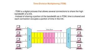
TDM and FDM TDM (Time Division Multiplexing) and FDM (Frequency Division Multiplexing) are two methods of multiplexing multiple signals into a single carrier. Multiplexing is the process of combining multiple signals into one, in such a manner that each individual signal can be retrieved at the destination. Since multiple signals are occupying the channel, they need to share the resource in some manner.
TDM and FDM The primary difference between FDM and TDM is how they divide the channels. FDM divides the channel into two or more frequency ranges that do not overlap. TDM divides and allocates certain time periods to each channel in an alternating manner. Because of this fact, we can say that TDM, each signal uses all of the bandwidth some of the time, while for FDM, each signal uses a small portion of the bandwidth all of the time.
TDM and FDM 1. FDM divides the channel into multiple, but smaller frequency ranges to accommodate more users, while TDM divides a channel by allocating a time period for each channel. 2. TDM provides much better flexibility compared to FDM. 3. FDM proves much better latency compared to TDM. 4. TDM and FDM can be used in tandem.
Reasons for Network Testing Verify that the design meets key business and technical goals Validate LAN and WAN technology and device selections Verify that a service provider provides the agreed- up service Identify bottlenecks or connectivity problems Determine optimization techniques that will be necessary
Reasons for Network Testing Proving that your network design is better than a competing design Passing an acceptance test that gives you approval to go forward with the network implementation Reassure mangers and co-workers that your design is effective Identifying any risks that might impede implementation and planning for contingencies Determine how much additional testing might be required. Will the new system be deployed as a pilot and undergo additional testing before being implemented
Testing Your Network Design Use industry testing services Build and test a prototype system Use third-party and Cisco tools
Respected Independent Test Labs Network Testing Labs' experts write hardware and software product reviews, state-of-the-art analyses, feature articles, in-depth technology workshops, cover stories, buyer s guides and in-depth technology outlooks. Experts have spoken on a number of topics at Comdex, Interop, PC Expo and other venues. In addition, they've created industry standard network benchmark software, database benchmark software and network diagnostic utilities.
Respected Independent Test Labs The Interoperability Lab at the University of New Hampshire (IOL) ICSA Labs Miercom Labs AppLabs The Tolly Group Penetration Testing test your network and applications before the bad guys do.
Simple verses Complex Network Designs Simple network designs can rely on test results from vendors, independent labs, or trade journals to prove to your customer that your design will perform as intended. Complex network designs require more considerations. Testing should be implemented in-house Testing will require more than component testing. There will be a need for unit, integration, and system testing.
Scope of a Prototype System Normally, it is impractical to implement a full-scale network system. A prototype should verify important capabilities and functions that might not perform adequately. Risky functions include complex, intricate functions and functions that were influenced by the need to make tradeoffs with other network components.
Live Production Network Perform initial testing during off-hours to minimize issues with user community, performance, and existing traffic flow. Perform final testing during normal hours and benchmark the performance. Perform final testing at various times to exercise the network during typical loads and benchmark the performance.
Test Plan Implement a Test Plan? A test plan is primarily comprised of test cases and test items. Think of a test case as a scenario or a finite state in which your network might find itself. In each test case, you'll have a list of test items or functions or features that you want to evaluate. Each test item should include not just an action, but the success criteria, and if you want to get more sophisticated, the testing too must be more critical. For example, you might want to make sure a business-critical application still work after a network change. So you'd arrange to have the application owners create a transaction or operate the application.
Components of a Test Plan Test objectives and acceptance criteria The types of tests that will be run Network equipment and other resources required Testing scripts The timeline and milestones for the testing a project
Components of a Test Plan Test objectives and acceptance criteria Objectives and acceptance should be based on a customer s business and technical goals Acceptance of test results are acceptable by both the customer and the tester. Measure response time Measure applications throughput Measure the amount of time it takes to hear a dial tone using Voice over IP Establish a baseline measurement of CRC errors
Test Objectives and Acceptance Criteria for a Test Plan Specific and concrete Based on business and technical goals Clear criteria for declaring that a test passed or failed Avoid biases and preconceived notions about outcomes If appropriate, reference an established baseline
Test Plan Considerations and Implementation Network Connectivity Section Is Layer 2 set up appropriately? (VLANs on the right trunks, PVCs, etc.) Do your router tables have the proper routes? (Check the next hops and ages, too.) Can you ping everywhere in the network? (Performance: Are the times acceptable?) Do trace routes show paths you would expect? If you load balance across the core of your network, verify each link is being used. Is DHCP handing out addresses? DNS resolving names properly? Does your remote access still work?
Test Plan Considerations Application Connectivity Section Does VOIP work? Is it showing up in the right queues? Are your firewalls and proxies blocking and allowing traffic appropriately? Can you browse the Web? Are your network management and logging systems working? Do your business applications work? (And do transactions complete in an acceptable time?) Are backup jobs still working?
Achieve Success with a New Network Design Your chances of success are much greater if you perform several simple tests along the way, rather than waiting until you think you're done and discovering that something doesn't work. Performing simple incremental tests along the way will help testers and customers maintain a sense of truthfulness and confidence about in the system being tested.
Types of Tests Application response-time tests with terminal Throughput tests (I/O) Availability tests (failure test) Regression tests (does the network perform similarly after changes were implemented)
Types of Tests What are the benefits of Protocol Testing? To understand the behavior of a protocol, it must be tested to observe the protocol s functionality Verify every phase of testing life cycle for Functionality testing Interoperability testing (IOT) is the process of testing to determine the interoperability of a software product Performance Obtain tools to generate and test the protocol messages
Types of Tests Why is Protocol Testing necessary? Different vendor products need to communicate with each other. If any product is using this standards in their devices they are interoperable with other vendor devices as both must meet compliance to Standards of IETF/RFC to study the network through their packet data. Protocol testing ensures proper functionality of various elements of a message. It also ensures whether it was designed as per specification.
Resources Needed for Testing A Test Plan should include a network topology drawing for tester to be able to reference. A list of switches, routers, bridges, firewalls, servers, telephone equipment, and wireless access points. A list of documented version numbers for hardware and software. Scheduled time in a lab either at your site or the customer s site Power, air conditioning, rack space, and other physical resources Help from co-workers or customer staff Help from users to test applications Network addresses and names
Resources Needed for Testing How it is carried out? Objective: To test the protocol i.e. to check every node with their packet data. Tools: Protocol Analyzer or WireShark and simulator.
Example Test Script Workstations Server 1 Firewall Network A Network B Protocol Analyzer Protocol Analyzer
Example Test Script (continued) Based on the previous slide Test objective. Assess the firewall s capability to block Application ABC traffic, during both light and moderately heavy load conditions. Acceptance criterion. The firewall should block the TCP SYN request from every workstation on Network A that attempts to set up an Application ABC session with Server 1 on Network B. The firewall should send each workstation a TCP RST (reset) packet.
Example Test Script (continued) 1. Start capturing network traffic on the protocol analyzer on Network A. 2. Start capturing network traffic on the protocol analyzer on Network B. 3. Run Application ABC on a workstation located on Network A and access Server 1 on Network B. 4. Stop capturing network traffic on the protocol analyzers.
Example Test Script (continued) 5. Display data on Network A s protocol analyzer and verify that the analyzer captured a TCP SYN packet from the workstation. Verify that the network layer destination address is Server 1 on Network B, and the destination port is port 1234 (the port number for Application ABC). Verify that the firewall responded to the workstation with a TCP RST packet.
Example Test Script (continued) 6. Display data on Network B s protocol analyzer and verify that the analyzer did not capture any Application-ABC traffic from the workstation. 7. Log the results of the test in the project log file. 8. Save the protocol-analyzer trace files to the project trace- file directory. 9. Gradually increase the workload on the firewall, by increasing the number of workstations on Network A one at a time, until 50 workstations are running Application ABC and attempting to reach Server 1. Repeat steps 1 through 8 after each workstation is added to the test.
Example Test Script (continued) Host A sends a TCP SYNchronize packet to Host B Host B receives A's SYN Host B sends a SYNchronize-ACKnowledgement Host A receives B's SYN-ACK Host A sends ACKnowledge Host B receives ACK. TCP socket connection is ESTABLISHED.
Tools for Testing a Network Design Network-management and monitoring tools. These monitoring tools are used to alert network management to problems and report significant network problems. Traffic generation tools Modeling and simulation tools QoS and service-level management tools Protocol analyzer
Tools for Testing a Network Design The following list of products are probably more related to network monitoring than network design, but don't forget that two important steps in the top-down network design methodology are characterizing the existing network and testing the new network. Big Brother Professional Edition Ixia IxN2X Multiservice Test Solution LANSurveyor Multi Router Traffic Grapher Nagios NetIQ
Tools for Testing a Network Design Online Erlang Traffic Calculators OPNET Orion NetFlow Traffic Analyzer (NTA) NetMRI Tivoli Visio Enterprise Network Tools WANDL's Network-Planning and Analysis Tools WhatsUp Gold
Protocol Analyzer Tool A protocol analyzer is used to analyze traffic behavior, errors, utilization, efficiency, and rates of broadcast and multicast packets. A protocol analyzer can be a computer program (WireShark) or a piece of computer hardware that can intercept and log traffic passing over a digital network or part of a network. As data streams flow across the network, the sniffer captures each packet and, if needed, decodes the packet's raw data, showing the values of various fields in the packet, and analyzes its content according to the appropriate RFC or other specifications.
Simulation Tool A simulation tool enables you to develop a model of a network, estimate the performance of the network and compare alternatives for implementing the network. iTrinegy Network Emulator (INE) products enable you to realistically recreate a wide variety of network conditions like latency, jitter, packet loss/error/reordering and bandwidth restrictions so that you can simulate environments such as Wide Area Networks (WANs), Wireless LANs, GPRS, 3G, IP over Radio/Radio over IP(RoIP), Satellite or MPLS networks.
Command Tools Test Tools: Command Format ipconfig ping <IP address> ping <DNS name> tracert <DNS name> nslookup <DNS name> nslookup yahoo.com netstat ping ping yahoo.com tracert yahoo.com netstat -a
Reasons to Optimize Meet key business and technical goals Use bandwidth efficiently Control delay and jitter Reduce serialization delay Support preferential service for essential applications Meet Quality of Service (QoS) requirements (IP Multicast)
IP Multicast Server Server
IP Multicast Router/MCS The Miscellaneous Control Subsystem (MCS) works with its companion Routing Engine provides control and monitoring functions for router components. It also generates a clock signal for the SONET/SDH interfaces on the router.
IP Multicast Applications Applications that take advantage of multicast include video conferencing, corporate communications, distance learning, and distribution of software, stock quotes, and news.
IP Multicast Helps Optimize Bandwidth Usage With IP multicast, you can send a high-volume multimedia stream just once instead of once for each user Requires support for Multicast addressing Multicast registration (IGMP) Multicast routing protocols
IP Multicast Addresses IPv4 Multicast Addresses 224.0.0.0 to 239.255.255.255 IPv6 Multicast Addresses FF02:0:0:0:0:0:0:1 All Nodes Address FF02:0:0:0:0:0:0:2 All Routers Address
IP Multicast Helps Optimize Bandwidth Usage To map an IP multicast address to a MAC- layer multicast address, the low order 23 bits of the IP multicast address are mapped directly to the low order 23 bits in the MAC-layer multicast address. Because the first 4 bits of an IP multicast address are fixed according to the class D convention, there are 5 bits in the IP multicast address that do not map to the MAC-layer multicast address.
IP Multicast Addressing Uses Class D multicast destination address 224.0.0.0 to 239.255.255.255 Converted to a MAC-layer multicast destination address The low-order 23 bits of the Class D address become the low-order 23 bits of the MAC-layer address The top 9 bits of the Class D address are not used The top 25 bits of the MAC-layer address are 0x01:00:5E followed by a binary 0
Internet Group Management Protocol (IGMP) Allows a host to join a multicast group Host transmits a membership-report message to inform routers on the segment that traffic for a group should be multicast to the host s segment IGMPv2 has support for a router more quickly learning that the last host on a segment has left a group
Multicast Routing Protocols Becoming obsolete Multicast OSPF (MOSPF) Distance Vector Multicast Routing Protocol (DVMRP) Still used Protocol Independent Multicast (PIM) Dense-Mode PIM Sparse-Mode PIM


")
")
")
")
")