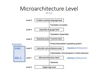
Computer Systems Architecture: Processor Microarchitecture Overview
Fundamental concepts of computer systems architecture, focusing on processor microarchitecture. Delve into the hardware-software interface, digital design, computer architecture, and system operations. From building a computing machine to discussing the von Neumann model, discover the key ideas and innovations that have shaped modern computing systems.

Download Presentation

Please find below an Image/Link to download the presentation.
The content on the website is provided AS IS for your information and personal use only. It may not be sold, licensed, or shared on other websites without obtaining consent from the author.If you encounter any issues during the download, it is possible that the publisher has removed the file from their server.
You are allowed to download the files provided on this website for personal or commercial use, subject to the condition that they are used lawfully. All files are the property of their respective owners.
The content on the website is provided AS IS for your information and personal use only. It may not be sold, licensed, or shared on other websites without obtaining consent from the author.
E N D
Presentation Transcript
CS152: Computer Systems Architecture Processor Microarchitecture Sang-Woo Jun Winter 2019 Large amount of material adapted from MIT 6.004, Computation Structures , Morgan Kaufmann Computer Organization and Design: The Hardware/Software Interface: RISC-V Edition , and CS 152 Slides by Isaac Scherson
Course outline Part 1: The Hardware-Software Interface o What makes a good processor? o Assembly programming and conventions Part 2: Recap of digital design o Combinational and sequential circuits o How their restrictions influence processor design Part 3: Computer Architecture o Simple and pipelined processors o Computer Arithmetic o Caches and the memory hierarchy Part 4: Computer Systems o Operating systems, Virtual memory
How to build a computing machine? Pretend the computers we know and love have never existed We want to build an automatic computing machine to solve mathematical problems Starting from (almost) scratch, where you have transistors and integrated circuits but no existing microarchitecture o No PC, no register files, no ALU How would you do it? Would it look similar to what we have now?
Aside: Dataflow architecture Instead of a PC traversing over instructions to execute, all instructions are independent, and are each executed whenever operands are ready o Programs are represented as graphs (with dependency information) Did not achieve market success, (why?) but the ideas are now everywhere e.g., Out-of-Order microarchitecture A static dataflow architecture
The von Neumann Model Almost all modern computers are based on the von Neumann model o John von Neumann, 1945 Components o Main memory, where both data and programs are held o Processing unit, which has a program counter and ALU o Storage and I/O to communicate with the outside world Key idea! Central Processing Unit Main Memory Storage and I/O
Key Idea: Stored-Program Computer Very early computers were programmed by manually adjusting switches and knobs of the individual programming elements o (e.g., ENIAC, 1945) von Neumann Machines instead had a general-purpose CPU, which loaded its instructions also from memory o Express a program as a sequence of coded instructions, which the CPU fetches, interprets, and executes o Treating programs as data Similar in concept to a universal Turing machine (1936) ENIAC, Source: US Army photo
von Neumann and Turing machine Turing machine is a mathematical model of computing machines o Proven to be able to compute any mechanically computable functions o Anything an algorithm can compute, it can compute Components include o An infinite tape (like memory) and a header which can read/write a location o A state transition diagram (like program) and a current location (like pc) State transition done according to current value in tape Only natural that computer designs gravitate towards provably universal models Source: Manolis Kamvysselis
Stored program computer, now what? Once we decide on the stored program computer paradigm o With program counter (PC) pointing to encoded programs in memory Then it becomes an issue of deciding the programming abstraction o Instruction set architecture, which we talked about Then, it becomes an issue of executing it quickly and efficiently o Microarchitecture! Improving performance/efficiency/etc while maintaining ISA abstraction o Which is the core of this class, starting now
A high-level view of computer architecture CPU Low latency (~1 cycle) Instruction cache Data cache Shared cache DRAM High latency (100s~1000s of cycles) Will deal with caches in detail later!
Remember: Super simplified processor operation inst = mem[PC] next_PC = PC + 4 if ( inst.type == STORE ) mem[rf[inst.arg1]] = rf[inst.arg2] if ( inst.type == LOAD ) rf[inst.arg1] = mem[rf[inst.arg2]] if ( inst.type == ALU ) rf[inst.arg1] = alu(inst.op, rf[inst.arg2], rf[inst.arg3]) if ( inst.type == COND ) next_PC = rf[inst.arg1] PC = next_PC
The classic RISC pipeline Many early RISC processors had very similar structure o MIPS, SPARC, etc o Major criticism of MIPS is that it is too optimized for this 5-stage pipeline RISC-V is also typically taught using this structure as well Write Back Fetch Decode Execute Memory Why these 5 stages? Why not 4 or 6?
The classic RISC pipeline Fetch: Request instruction fetch from memory Decode: Instruction decode & register read Execute: Execute operation or calculate address Memory: Request memory read or write Writeback: Write result (either from execute or memory) back to register
Designing a microprocessor Many, many constraints processors are optimize for, but for now: Constraint 1: Circuit timing o Processors are complex! How do we organize the pipeline to process instructions as fast as possible? Constraint 2: Memory access latency o Register files can be accessed as a combinational circuit, but it is small o All other memory have high latency, and must be accessed in separate request/response Memory can have high throughput, but also high latency Memory will be covered in detail later!
The most basic microarchitecture Because memory is not combinational, our RISC ISA requires at least three disjoint stages to handle o Instruction fetch o Instruction receive, decode, execute (ALU), register file access, memory request o If mem read, write read to register file Three stages can be implemented as a Finite State Machine (FSM) Register File Instruction Decoder PC ALU Will this processor be fast? Why or why not? Memory Interface
Limitations of our simple microarchitecture Stage two is disproportionately long o Very long critical path, which limits the clock speed of the whole processor o Stages are not balanced Note: we have not pipelined things yet! *Critical path depends on the latency of each component Register File Instruction Decoder PC ALU Memory Interface
Limitations of our simple microarchitecture Let s call our stages Fetch( F ), Execute( E ), and Writeback ( W ) Speed of our simple microarchitecture, assuming: o Clock-synchronous circuits, single-cycle memory Lots of time not spent doing useful work! o Can pipelining help with performance? time instr. 1 F E W F E W instr. 2 Clock cycle due to critical path of Execute
Pipelined processor introduction Attempt to pipeline our processor using pipeline registers/FIFOs Fetch Execute Writeback * We will see soon why pipelining a processor isn t this simple Much better latency and throughput! o Average CPI reduced from 3 to 1! o Still lots of time spent not doing work. Can we do better? time instr. 1 F F E E W W F E W F E W instr. 2 Note we need a memory interface with two concurrent interfaces now! (For fetch and execute) Remember instruction and data caches!
Building a balanced pipeline Must reduce the critical path of Execute Writing ALU results to register file can be moved to Writeback o Most circuitry already exists in writeback stage o No instruction uses memory load and ALU at the same time RISC! Register File Instruction Decoder PC ALU Memory Interface
Building a balanced pipeline Divide execute into multiple stages o Decode Extract bit-encoded values from instruction word Read register file o Execute Perform ALU operations o Memory Request memory read/write No single critical path which reads and writes to register file in one cycle Fetch Decode Execute Execute Memory Writeback Results in a small number of stage with relatively good balance!
Ideally balanced pipeline performance Clock cycle: 1/5 of total latency Circuits in all stages are always busy with useful work time instr. 1 Fetch Decode Execute Memory Writeback instr. 2 Fetch Decode Execute Memory Writeback instr. 3 Fetch Decode Execute Memory Writeback
Aside: Real-world processors have wide range of pipeline stages Name Stages AVR/PIC microcontrollers 2 ARM Cortex-M0 3 Apple A9 (Based on ARMv8) 16 Original Intel Pentium 5 Intel Pentium 4 30+ Intel Core (i3,i5,i7, ) 14+ RISC-V Rocket 6 Designs change based on requirements!
Will our pipeline operate correctly? Register File Fetch Decode Execute Memory Writeback Memory Interface
A problematic example What should be stored in data+8? 3, right? Assuming zero-initialized register file, our pipeline will write zero Why? Hazards
Hazard #1: Read-After-Write (RAW) Data hazard When an instruction depends on a register updated by a previous instruction s execution results o e.g., i1: add s0, s1, s2 i2: add s3, s0, s4 Register File Fetch Decode Execute Memory Writeback Cycle 1 Cycle 2 i1 reads s1, s2 Cycle 3 i2 reads s0, s4 i1 calculates s0
Hazard #1: Read-After Write (RAW) Hazard i1: addi s0, zero, 1 i2: addi s1, s0, 0 s0 should be 1, s1 should be 1 Fetch Decode Execute Memory Writeback Cycle 1 s0 = 0 Cycle 2 s0 = 0 i2 reads s0, but s0 is still zero! Cycle 3 s0 = 0 s0 = 0 Cycle 4 s0 = 0 Cycle 5 s0 = 1 Cycle 6
Solution #1: Stalling The processor can choose to stall decoding when RAW hazard detected Sacrifices too much performance! i1: add s0, s1, s2 Register File i2: add s3, s0, s4 Fetch Decode Execute Memory Writeback Cycle 1 Cycle 2 i1 reads s1, s2 Pipeline bubbles Cycle 5 Cycle 6 i1 writing s0 i2 not decoded i1 retired i2 reads s0
i1: addi s0, zero, 1 Solution #1: Stalling i2: addi s1, s0, 0 Fetch Decode Execute Memory Writeback Cycle 1 s0 = 0 Cycle 2 s0 = 0 i2 stalled until s0 is applied Cycle 3 s0 = 0 Pipeline bubble Wasted cycles s0 = 0 Cycle 4 s0 = 0 Cycle 5 s0 = 1 Cycle 6 s0 = 1 Cycle 7 i2 reads correct s0 Sacrifices too much performance!
Solution #2: Forwarding (aka Bypassing) Forward execution results to input of decode stage o New values are used if write index and a read index is the same i1: add s0, s1, s2 Register File i2: add s3, s0, s4 Fetch Decode Execute Memory Writeback Cycle 1 Cycle 2 i1 reads s1, s2 Cycle 3 i2 reads s0, s4 But! Uses new s0 forwarded from execute i1 calculates s0 No pipeline stalls!
Solution #2: Forwarding details May still require stalls for a deeper pipeline microarchitecture o If execute took many cycles? Adds combinational path from execute to decode o But does not imbalance pipeline very much! Register File Fetch Decode Execute Memory Writeback Instruction bit decode Register file access Execute Question: How does hardware detect hazards? Combinational path only to end of decode stage!
i1: addi s0, zero, 1 Solution #2:Forwarding i2: addi s1, s0, 0 results forwarded to decode within same cycle Fetch Decode Execute Memory Writeback Cycle 1 s0 = 0 Cycle 2 s0 = 0 s0 is still zero, but i1 results forwarded to i2 Cycle 3 s0 = 0 s0 = 0 Cycle 4 s0 = 0 Cycle 5 s0 = 1 Cycle 6 Forwarding is possible in this situation because the answer (s0 = 1) exists somewhere in the processor!
Datapath with Hazard Detection Not very intuitive We will revisit with code later
Hazard #2: Load-Use Data Hazard When an instruction depends on a register updated by a previous instruction o e.g., i1: lw s0, 0(s2) i2: addi s1, s0, 1 Forwarding doesn t work here, as loads only materialize at writeback o Only architectural choice is to stall Register File Fetch Decode Execute Memory Writeback
i1: lw s0, 0(s2) Hazard #2: Load-Use Data Hazard i2: addi s1, s0, 1 Fetch Decode Execute Memory Writeback Cycle 1 s0 = 0 Cycle 2 s0 = 0 i2 stalled until s0 is updated Cycle 3 s0 = 0 s0 = 0 Cycle 4 s0 = 0 Cycle 5 s0 = 1 Cycle 6 s0 = 1 Cycle 7 i2 reads correct s0 Forwarding is not useful because the answer (s0 = 1) exists outside the chip (memory)
A non-architectural solution: Code scheduling by compiler Reorder code to avoid use of load result in the next instruction e.g., a = b + e; c = b + f; lw lw add sw lw add sw x1, 0(x0) x2, 8(x0) x3, x1, x2 x3, 24(x0) x4, 16(x0) x5, x1, x4 x5, 32(x0) lw lw lw add sw add sw x1, 0(x0) x2, 8(x0) x4, 16(x0) x3, x1, x2 x3, 24(x0) x5, x1, x4 x5, 32(x0) stall stall 20 cycles 14 cycles Compiler does best, but not always possible!
Review: A problematic example RAW hazard RAW hazard RAW hazard Load-Use hazard RAW hazard Note: la is not an actual RISC-V instruction o Pseudo-instruction expanded to one or more instructions by assembler o e.g., auipc x5,0x1 addi x5,x5,-4 # RAW hazard!
Other potential data hazards Read-After-Write (RAW) Hazard o Obviously dangerous! -- Writeback stage comes after decode stage o (Later instructions reads cancome before earlier instructions write) Write-After-Write (WAW) Hazard o No hazard for in-order processors Write-After-Read (WAR) Hazard o No hazard for in-order processors -- Writeback stage comes after decode stage o (Later instructions reads cannotcome before earlier instructions write) Read-After-Read (RAR) Hazard? o No hazard within processor 3 cycle difference read rf write rf Fetch Decode Execute Memory Writeback
Hazard #3: Control hazard Branch determines flow of control o Fetching next instruction depends on branch outcome o Pipeline can t always fetch correct instruction e.g., Still working on decode stage of branch i1: beq s0, zero, elsewhere i2: addi s1, s0, 1 PC Fetch Decode Execute Memory Writeback Cycle 1 Cycle 2 Should I load this or not?
Control hazard (partial) solutions Branch target address can be forwarded to the fetch stage o Without first being written to PC o Still may introduce (one less, but still) bubbles PC Fetch Decode Execute Memory Writeback Decode stage can be augmented with logic to calculate branch target o May imbalance pipeline, reducing performance o Doesn t help if instruction memory takes long (cache miss, for example)
Aside: An awkward solution: Branch delay slot In a 5-stage pipeline with forwarding, one branch hazard bubble is injected in best scenario Original MIPS and SPARC processors included branch delay slots o One instruction after branch instruction was executed regardless of branch results o Compiler will do its best to find something to put there (if not, nop ) Goal: Always fill pipeline with useful work Reality: o Difficult to always fill slot o Deeper pipelines meant one measly slot didn t add much (Modern MIPS has 5+ cycles branch penalty!) But once it s added, it s forever in the ISA One of the biggest criticisms of MIPS
Eight great ideas Design for Moore s Law Use abstraction to simplify design Make the common case fast Performance via parallelism Performance via pipelining Performance via prediction Hierarchy of memories Dependability via redundancy
Control hazard and pipelining Solving control hazards is a fundamental requirement for pipelining o Fetch stage needs to keep fetching instructions without feedback from later stages o Must keep pipeline full somehow! o Can t know what to fetch Fetch Decode Execute Memory Writeback Cycle 1 Fetch PC = 0 Cycle 2 Fetch PC = ? Decode PC = 0
Control hazard (partial) solution Branch prediction We will try to predict whether branch is taken or not o If prediction is correct, great! o If not, we somehow do not apply the effects of mis-predicted instructions (Effectively same performance penalty as stalling in this case) o Very important to have mispredict detection before any state change! Difficult to revert things like register writes, memory I/O Simplest branch predictor: Predict not taken o Fetch stage will keep fetching pc <= pc + 4 until someone tells it not to
Predict not taken example Fetch Decode Execute Memory Writeback addi Mispredict detected! addi addi beq addi addi sw t3 beq addi addi ret sw t3 beq addi addi sw t2 beq addi Pipeline bubbles Fetch correct branch No state update before Execute stage can detect misprediction (Fetch and Decode stages don t write to register)
How to handle mis-predictions? Implementations vary, each with pros and cons o Sometimes, execute sends a combinational signal to all previous stages, turning all instructions into a nop A simple method is epoch-based o All fetched instructions belong to an epoch , represented with a number o Instructions are tagged with their epoch as they move through the pipeline o In the case of mis-predict detection, epoch is increased, and future instructions from previous epochs are ignored
Predict not taken example with epochs epoch = 0 epoch = 1 Fetch Decode Execute Memory Writeback addi (0) Mispredict detected! addi (0) addi (0) beq (0) addi (0) addi (0) sw t3 (0) beq (0) addi (0) addi (0) ret (0) sw t3 (0) beq (0) addi (0) addi (0) ret (0) sw t3 (0) sw t2 (1) beq (0) addi (0) ret (0) ret (1) sw t2 (1) beq (0) Ignored Ignored sw t2 (1) Fetch correct branch ret (1)
Some classes of branch predictors Static branch prediction o Based on typical branch behavior o Example: loop and if-statement branches Predict backward branches taken Predict forward branches not taken Dynamic branch prediction o Hardware measures actual branch behavior e.g., record recent history (1-bit taken or not taken ) of each branch in a fixed size branch history table o Assume future behavior will continue the trend When wrong, stall while re-fetching, and update history Many many different methods, Lots of research, some even using neural networks!
Branch prediction and performance Effectiveness of branch predictors is crucial for performance o Spoilers: On SPEC benchmarks, modern predictors routinely have 98+% accuracy o Of course, less-optimized code may have much worse behavior Branch-heavy software performance depends on good match between software pattern and branch prediction o Some high-performance software optimized for branch predictors in target hardware o Or, avoid branches altogether! (Branchless code)
Aside: Impact of branches [This code] takes ~12 seconds to run. But on commenting line 15, not touching the rest, the same code takes ~33 seconds to run. (running time may wary on different machines, but the proportion will stay the same). Source: Harshal Parekh, Branch Prediction Everything you need to know.
Aside: Impact of branches Slower because it involves two branches Source: Harshal Parekh, Branch Prediction Everything you need to know.


")


")


 solutions")


 solution")