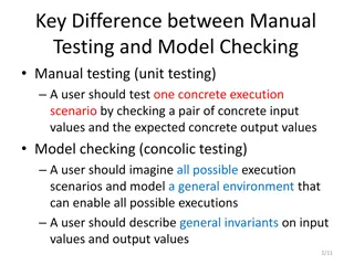
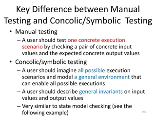
Concolic Execution & Testing Programs
Concolic execution is a powerful method combining concrete and symbolic inputs to test software effectively. Learn about its steps, applications, limitations, and historical development in program validation methods.

Download Presentation

Please find below an Image/Link to download the presentation.
The content on the website is provided AS IS for your information and personal use only. It may not be sold, licensed, or shared on other websites without obtaining consent from the author.If you encounter any issues during the download, it is possible that the publisher has removed the file from their server.
You are allowed to download the files provided on this website for personal or commercial use, subject to the condition that they are used lawfully. All files are the property of their respective owners.
The content on the website is provided AS IS for your information and personal use only. It may not be sold, licensed, or shared on other websites without obtaining consent from the author.
E N D
Presentation Transcript
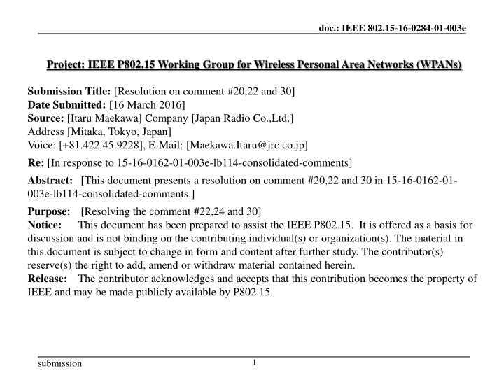
doc.: IEEE 802.15-16-0284-01-003e Project: IEEE P802.15 Working Group for Wireless Personal Area Networks (WPANs) Submission Title: [Resolution on comment #20,22 and 30] Date Submitted: [16 March 2016] Source: [Itaru Maekawa] Company [Japan Radio Co.,Ltd.] Address [Mitaka, Tokyo, Japan] Voice: [+81.422.45.9228], E-Mail: [Maekawa.Itaru@jrc.co.jp] Re: [In response to 15-16-0162-01-003e-lb114-consolidated-comments] Abstract: [This document presents a resolution on comment #20,22 and 30 in 15-16-0162-01- 003e-lb114-consolidated-comments.] Purpose: [Resolving the comment #22,24 and 30] Notice: This document has been prepared to assist the IEEE P802.15. It is offered as a basis for discussion and is not binding on the contributing individual(s) or organization(s). The material in this document is subject to change in form and content after further study. The contributor(s) reserve(s) the right to add, amend or withdraw material contained herein. Release: The contributor acknowledges and accepts that this contribution becomes the property of IEEE and may be made publicly available by P802.15. 1 submission
<Mar. 2016> doc.: IEEE 802.15-16-0284-01-003e Comment and the resolution Comment #22 Page Sub- Line # Proposed Change clause How does the LLPS mode work when the LLPS Capable flag is set in a) PPC Capability IE or b) DEV Capability IE? Add detail description to enable LLPC mode. 42 6.4.11a 4 Slide 2 Maekawa, et al. (JRC) submission
Figure 6-88bPPC Capability field <Mar. 2016> doc.: IEEE 802.15-16-0284-01-003e Capability field in D01 -It is not clear in D01, who decides LLPS parameters. -LLPS Parameters should be specified by Coordinator because coordinator know higher layer application. Slide 3 Maekawa, et al. (JRC) submission
Figure 6-88bPPC Capability field <Mar. 2016> doc.: IEEE 802.15-16-0284-01-003e Resolution Accept the comment and change the text and Figure as follows -Change the name from LLPS Capability to LLPS Allow -6-88b(PPC Capability): Re-order capability field alignment. -6-88i(DEV Capability): Use common definition with 6-88b then change LLPS parameters fields to reserved -6-88(Pair Capability): Use common definition with 6-88b then change LLPS parameters fields to reserved . -P44 -P47 :Delete following sentences -P48 : Delete following sentences Slide 4 Maekawa, et al. (JRC) submission
<Mar. 2016> doc.: IEEE 802.15-16-0284-01-003e Comment and the resolution Comment #24 Page Sub- Line # Proposed Change clause Is it possible to issue a sleep request from either PPC or DEV? Make clear the start condition and definition of the HRCP DEV. 64 7.14a 16 Slide 5 Maekawa, et al. (JRC) submission
Figure 6-88bPPC Capability field <Mar. 2016> doc.: IEEE 802.15-16-0284-01-003e Resolution Accept the comment and revice the text as follows Slide 6 Maekawa, et al. (JRC) submission
<Mar. 2016> doc.: IEEE 802.15-16-0284-01-003e Comment and the resolution Comment #30 Page Sub- Line # Proposed Change clause It appears redundant to send empty data frames to adjust the subframe number and subframe length. There should be a better way to do this. Clarify meaning. 61 7.8.3 9 Resolution 1)Delete paragraph. 2)In Fig 7-54a and 7-54b, Change "More fragment flag is set to 1 to indicate the corresponding subframe is not a final frame of fragmentation." to "Last fragment flag is set to 1 to indicate the corresponding subframe is a final frame of fragmentation." Change "More fragment" to "Last fragment" in all other appropriate locations in the draft. (in 6.3.4a.1 as well) 3)Add new text to explain the size requirement for each subframe. A MPDU which is not a last fragment of an original MSDU, shall have a payload with the length of the Preferred Payload Size in Pair Capability field. Slide 7 Maekawa, et al. (JRC) submission
<Mar. 2016> doc.: IEEE 802.15-16-0284-01-003e Resolution #1 -Delete paragraph on P61 ,line 9-12 To avoid buffer overflow, before starting real data transmission, the originating and target DEV may exchange empty data frame with the preferred total aggregation size properly configured as defined in 6.4.11 to inform each other the available receiving buffer size. This information is used by the DEVs to adjust the subframe number and subframe length when sending real data. Slide 8 Maekawa, et al. (JRC) submission
<Mar. 2016> doc.: IEEE 802.15-16-0284-01-003e Resolution #2 -Change More Fragment to Last Fragment on Page 61 line 7 to 8. -Change as follows on Page 39 Slide 9 Maekawa, et al. (JRC) submission
MSDU#1 MSDU#2 MSDU#3 doc.: IEEE 802.15-16-0284-01-003e Resolution #3 Fragmentation Fragmentation Payload#2 (Fragment#1) Payload#3 (Fragment#2) Payload#4 (Fragment#1) Payload#5 (Fragment#2) MAC Header Payload#1 Last fragment=1 MAC HCS FCS Payload#1 Subheader#1 Last fragment flag is set to 1 to indicate the corresponding subframe is a final frame of fragmentation. Subframe#1 Last fragment=0 MAC HCS FCS Payload#2 Subheader#2 Subframe#2 Last fragment=1 MAC HCS FCS Payload#3 Payload# and Payload length are shown in Sub Header Subheader#3 Last fragment=0 Subframe#3 MAC HCS Number of subframes and Ack information are shown in MAC Header FCS Payload#4 Subheader#4 Subframe#4 Subframe #1 m+1 Subframe #2 m+2 Subframe #3 m+3 Subframe #4 m+4 Subframe #n m+n HCS PHY Header MAC Header Sequence Number submission Slide10 (7-54a)
MSDU#1 MSDU#2 MSDU#3 doc.: IEEE 802.15-16-0284-01-003e Defragmentation Defragmentation Payload#2 (Fragment#1) Payload#3 (Fragment#2) Payload#4 (Fragment#1) Payload#5 (Fragment#2) MAC Header Payload#1 Last fragment=1 MAC HCS FCS Payload#1 Subheader#1 Last fragment flag is set to 1 to indicate the corresponding subframe is a final frame of fragmentation. Subframe#1 Last fragment=0 MAC HCS FCS Payload#2 Subheader#2 Subframe#2 Last fragment=1 MAC HCS FCS Payload#3 Payload# and Payload length are shown in Sub Header Subheader#3 Subframe#3 Last fragment=0 MAC Number of subframes and Ack information are shown in MAC Header HCS FCS Payload#4 Subheader#4 Subframe#4 Subframe #1 m+1 Subframe #2 m+2 Subframe #3 m+3 Subframe #4 m+4 Subframe #n m+n HCS PHY Header MAC Header Sequence Number submission Slide11 (7-54b)
<Mar. 2016> doc.: IEEE 802.15-16-0284-01-003e Resolution #3 -Add following sentence on Page 60. Slide 12 Maekawa, et al. (JRC) submission