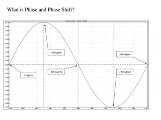
Critical Review of CTF3 Performance: Impressive Progress and Phase Optimization
The critical review showcases the impressive progress achieved by the CTF3 team despite operational challenges. It highlights advancements in beam phase optimization, stability enhancement, drive beam generation, and RF power generation. The evaluation covers phase variation, form factor variation, and beam phase evolution, emphasizing the ongoing efforts to optimize beam performance and maintain stability.

Uploaded on Mar 08, 2025 | 1 Views
Download Presentation

Please find below an Image/Link to download the presentation.
The content on the website is provided AS IS for your information and personal use only. It may not be sold, licensed, or shared on other websites without obtaining consent from the author.If you encounter any issues during the download, it is possible that the publisher has removed the file from their server.
You are allowed to download the files provided on this website for personal or commercial use, subject to the condition that they are used lawfully. All files are the property of their respective owners.
The content on the website is provided AS IS for your information and personal use only. It may not be sold, licensed, or shared on other websites without obtaining consent from the author.
E N D
Presentation Transcript
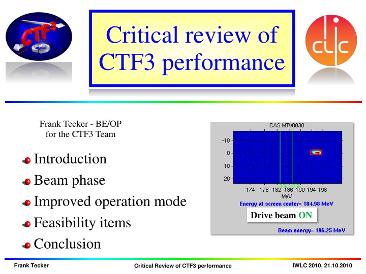
Critical review of CTF3 performance Frank Tecker - BE/OP for the CTF3 Team Introduction Beam phase Improved operation mode Feasibility items Conclusion Drive beam ON Frank Tecker IWLC 2010, 21.10.2010 Critical Review of CTF3 performance
Conclusion Impressive progress in short time! Important progress despite the fire operation with full Drive Beam generation consolidated stability issues addressed and stability improved CLIC current stability needs reached CLIC klystron stability demonstrated Beam Driven RF power generation as expected up to 200 MW generated in PETS structure (CLIC 135 MW nom.) bunch phase crucial still optimizing the combined beam First two-beam acceleration with 55 MV/m Many other points well covered many more detailed presentations on Wednesday and Thursday in WG6 (Drive beam complex and CTF3) Many Thanks to everyone who made this possible!!! Frank Tecker IWLC 2010, 19.10.2010 CTF3 results
Phase variation along the pulse Combined pulse generated by chopping and superimposing the long bunch train => bunch phase of individual bunches kept (for ideal combination) phase variation leads to power reduction in combined beam 2 2 <= Combined phase seems to vary little 1 1 Erik Adli Frank Tecker Critical Review of CTF3 performance IWLC 2010, 21.10.2010
Phase variation from combination Combination can be worsened by DL + CR path length error Example DL length error: Erik Adli we know the effects and we know how to correct Frank Tecker Critical Review of CTF3 performance IWLC 2010, 21.10.2010
Form factor variation we observe a form factor variation along the pulse here factor 4 beam (TBL from R.Lillest l) bunch phase / bunch length variation in addition: factor 8 combination gives lower form factor than factor 4 => additional complication of DL length (we know how to change) Frank Tecker Critical Review of CTF3 performance IWLC 2010, 21.10.2010
Beam phase evolution flat phase MKS02/phase sag MKS03 due to pulse compression => energy, bunch length and beam phase variation after chicane => have to optimize machine for full train CK.STPSI05P 2 1 0 -1 deg -2 compressed RF phase -3 -4 TL1 -5 5800 6000 6200 6400 6600 6800 7000 7200 7400 7600 7800 ns Injector Bunch length chicane Linac Compression chicane TL2 chicane Laser CLEX Frank Tecker Critical Review of CTF3 performance IWLC 2010, 21.10.2010
RF phase (presently) 1200 s Phase 0 flat phase along pulse for SHBs and pre-/buncher alternating phase sag for accelerating structures gives sufficiently low E/E if well optimized still: bunch length variation + bunch phase variation Frank Tecker Critical Review of CTF3 performance IWLC 2010, 21.10.2010
Phase evolution II Bunch length chicane has R56=0.45 m at the moment 1% E/E => 16.2 deg @ 3GHz phase => 65 deg @ 12 GHz => reduce R56 (but strong quads, more difficult) TL1 Injector Bunch length chicane Linac Compression chicane TL2 chicane Laser CLEX Frank Tecker Critical Review of CTF3 performance IWLC 2010, 21.10.2010
Energy/phase correlation Phase dominated by energy variation in stretcher chicane afterwards isochronous optics => phase stays constant Stretcher chicane Phase monitor CR Horizontal position => energy D=0.18m => ~1.5% E/E Phase monitor TL2 12 GHz phase TBL Frank Tecker Critical Review of CTF3 performance IWLC 2010, 21.10.2010
Energy variation minimized used RF pulse compression to minimize E/E after the linac D0608=0.61m => 13mm = ~2% to ~3mm = ~0.5% E/E Frank Tecker Critical Review of CTF3 performance IWLC 2010, 21.10.2010
Phase optimization this energy optimisation results in a phase optimisation 12 GHz RF phase 20 deg 100 deg Frank Tecker Critical Review of CTF3 performance IWLC 2010, 21.10.2010
RF phase proposal 1200 s Phase 0 same sag for SHBs and pre-/buncher + accelerating structures E/E = 0 along the pulse, no bunch length variation still: bunch phase variation could be compensated in Frascati or TL2 chicane (slight energy shaping along the pulse) tuning all along the pulse identical much less sensitive to phase errors [cos(~few deg)] Frank Tecker Critical Review of CTF3 performance IWLC 2010, 21.10.2010
DB generation mid 2011 Bunch train recombination Consolidate results, routine operation, stability of fully combined beam Transverse rms emittance Complete TL2, TL2 , TBTS commissioning full transport to CLEX < 100 mm mrad after ring, combined beam < 150 mm mrad in CLEX, combined beam Bunch length control to < 1 mm rms (combined beam) Measurement campaign with different meas. systems (RF defl.& screen, fast streak-camera, RF monitors) R56 tuning experiments in Frascati chicane and TL2 Beam current stability: improve slow variations, obtain ~0.2 % for combined beam Full measurement campaign (find correlations, jitter sources) Gun pulse flatness, slow feedback Improve overall klystron stability (at least up to best performing klystrons) Slow RF feedback (temp. in pulse compressors) Frank Tecker Slide # CTF3 Techn. Coll. Meeting, 5.5.2010
RF structures mid 2011 PETS TBTS Initial configuration with variable power splitter & phase shifter Fast fall-back solution: recirculation with no active elements (maximum power to accelerating structure) Goal: nominal power / pulse length inside PETS with recirculation (135 MW, 250 ns total pulse length, 170 ns flat-top) Breakdown rate measurements (at high BD rate - extrapolation to lower rates) Operation w/out recirculation may have different breakdown rate Test of new PETS on-off scheme (components and concept) Acc. structure in TBTS TD24, initial conditioning in the shadow of PETS operation Goal: nominal power / pulse length delivered to structure (65 MW, 250 ns total pulse length, 170 ns flat-top) Frank Tecker Slide # CTF3 Techn. Coll. Meeting, 5.5.2010
Two beam issues mid 2011 TBTS Two-Beam test 100 MV/m, consistency between power & beam energy gain Drive beam, deceleration, power produced Probe beam, power delivered to accelerating structure, energy gain Beam Loading compensation experiment - by varying fast phase switches check control of RF pulse shape with probe beam acceleration Measurement of breakdown kicks Measurement of effect of beam loading on breakdown rate TBL Measurement of deceleration / produced power Goal: deceleration by 30% (need 8 PETS installed) Measurement of energy spectrum Optics, steering algorithm studies Frank Tecker Slide # CTF3 Techn. Coll. Meeting, 5.5.2010
Other issues mid 2011 CALIFES Fully reach nominal parameters (total charge) Bunch length measurements (RF defl. & screen) PHIN 2010: complete measurement program 2011: test of phase coding with beam Other First measurements of phase stability (PETS output, RF pickups ) Operation at 5 Hz (or more) Control of beam losses Coherent Diffraction Radiation (RHUL collaboration) Frank Tecker Slide # CTF3 Techn. Coll. Meeting, 5.5.2010
Conclusion we understand how to improve power production primary goal: two-beam acceleration 100 MV/m (including RF power signals consistency and deceleration) complete the list of feasibility issues as much as possible new setup with increased current when MKS13 is available (2011) still a lot of work ahead Frank Tecker Slide # CTF3 Techn. Coll. Meeting, 5.5.2010
Spares Frank Tecker Slide # CTF3 Techn. Coll. Meeting, 5.5.2010
CTF3 experimental program, Plans for 2010 R. Corsini - 5th CLIC ACE, 2 February 2009 CTF3 2010 outlook Roberto s comments Feb 2010: Drive Beam Generation Will be OK, possibly somewhat reduced performance Bunch train recombination 2 x 4 in DL and CR (from 3.5 to 28 A) Transverse rms emittance < 150 mm mrad (combined beam) Bunch length control to < 1 mm rms (combined beam) Beam current stability ~ 0.1 % for combined beam Drive Beam Power Production & Two Beam Acceleration 20.8 A beam-powered test of a single PETS (without recirculation) in the TBTS 135 MW (with 28 A potentially available in CLEX, the peak power can reach 240 MW) 140 ns total pulse length A measured breakdown rate in the range of 10-4 or lower Operation of a few hundred hours at 1 Hz Overall reasonable goals, but difficult to have a few hundred hours, and 5 Hz 7.4(10) A beam-powered test of a single PETS with ext. recirculation in TBTS 135 (81) MW circulating power or 65 (65) MW available for accelerating testing 250 ns total pulse length, 100 (170) ns flattish-top A measured breakdown rate in the range of 10-4 or lower Operation of a few hundred hours at 5 Hz On/off/adjust will be demonstrated using the external reflection/recirculation system mounted on one of the PETS in TBL. TBTS TBTS studies and especially TBL results can happen only quite late in 2010 Improved measurements of power and energy loss. Breakdown transverse kick measurements. Probe Beam energy gain and beam loading tests. TBL The current schedule is to have 8 PETS installed as well as a spectrometer dump for energy spectrum studies, toward the summer 2010. This will allow to verify transport of a beam with up to 30% of the energy extracted.
Item list current stability combined beam TBL deceleration <100 MV/m acceleration emittance combined beam isochronicity DL + CR laser stability (PHIN) loss management, higher rep rate phase: linac, R56, path length DL + CR bunch compression TL2 RF power calibrations gun current along pulse Frank Tecker Critical Review of CTF3 performance IWLC 2010, 21.10.2010
DB scheme - status quite close to all requirements already at the end of 2009 Objective mid2011 Parameter Unit CLIC nominal Present state Objective2013 I initial A 4.2 5 I final A 100 28 30 Qb nC 8.4 4 (2.3 nom.) 100 (end of linac) 150 (y, comb. beam) mm mrad 150 Emittance, norm rms 150 (comb. beam) Bunch length mm 1 1 (comb. beam) E MeV 2400 120 150 s Tpulse initial Tpulse final Beam Load. Eff. 140 1.4 ns 240 140 (240) 140 (240) 140 (240) % 97 95 Deceleration 90 - 30 50 or more Phase stability @ 12 GHz 0.5 ? 0.2 degrees 0.2 - 7.510-4 to few 10- 5 Intensity stability 2 10-3 (comb.4) 2 10-3 (comb.8) 1 10-3 (comb.8) Frank Tecker Critical Review of CTF3 performance IWLC 2010, 21.10.2010


")