Current Density in Conduction and Convection Phenomena
Explore the concepts of convection and conduction current density in electromagnetism. Learn how charged particles give rise to current densities, the application of Ohm's law, and calculations involving resistance in conductors. Dive into the intricacies of current flow and conductivity in various materials.

Download Presentation

Please find below an Image/Link to download the presentation.
The content on the website is provided AS IS for your information and personal use only. It may not be sold, licensed, or shared on other websites without obtaining consent from the author. If you encounter any issues during the download, it is possible that the publisher has removed the file from their server.
You are allowed to download the files provided on this website for personal or commercial use, subject to the condition that they are used lawfully. All files are the property of their respective owners.
The content on the website is provided AS IS for your information and personal use only. It may not be sold, licensed, or shared on other websites without obtaining consent from the author.
E N D
Presentation Transcript
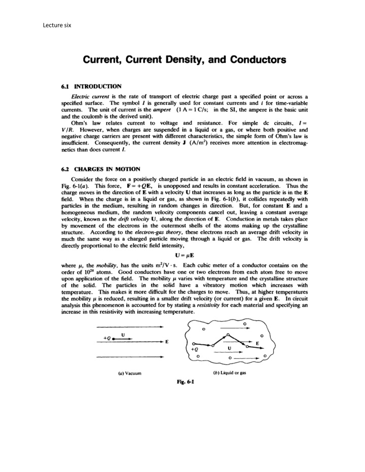
Lecture six 6.3 CONVECTION CURRENT DENSITY J A set of charged particles giving rise to a charge density p in a volum e v is shown in Fig. 6-2 to have a velocity U to the right. The particles arc assumed to maint ain their relative positions within the volume. As this charge configuration passes a surface S it constitutes a convection current, with density J "" p U (A/m2 ) Of course, if the cross section of v varies or if the density p is not constant throughout v, then J will not be constant with time. Further, J will be zero when the last portion of the volume crosses S. Nevertheless, the concept of a current density caused by a cloud of charged panicles in motion is at times useful in the study of electromagnetic field theory. - u J =pU s Fig. 6-2 6. 4 CONDUCfiON CURRENT DENSITY J Of more interest is the conduction current that occurs in the presence of an electric field within a conductor of fixed cross section. The current density is again given by J =pU (A/ m2 ) U = J,LE, can be written which, in view of the relation J = aE a =Pll is the conductivity of the material, in siemens p er meter (S/ m). where metallic conductors the charge carriers are electrons, which drift in a direction opposite to that of the electric field (Fig. 6-3). Hence, for electrons, both p a positive conductivity a, ju st as in the case of positive charge carriers. have the same direction regardless of the sign of the charge carriers. electrons moving to the left as positive charges moving to the right , and always to report p and p. as positive. The relation takes into account the density of the electrons free to move (p) and the relative ease with which they move through the crystalline structure (p.). As might be temperature. In and p. are negative, which results in It follows that J and E It is conventional to treat J =aE is often referred to as the pointform of Ohm's law. The factor a a is a function of expected, s Fig. 6-3
Lecture six 6.7 R RESISTANCE If a conductor of uniform cross-sectional area A and length t, asshown in Fig. 6-7. has a voltage difference V between its ends, then E=v and t assuming that the current is uniformly distributed over the area A then J =oV t The total current is I = JA = oAV t V=IR, Since Ohm's law states that the resistance is t R = oA (0) 1s- = I 0 ; (Note that for resistance is generally applied to all conductors where the cross section remains constant over the length t. However. if the current density is greater along the surface area of the conductor than in the center, then the expression is not distributions the resistance is given by R = =- - - JJ dS IoE dS the siemens was formerly known as the mho.) This expression v valid. v For such nonuniform current If E is known rather than the voltage difference between the two faces, the resistance isgiven by IE d l R = - - - - foE dS The numerator gives the voltage drop across the sample, while the denominator gives the total current I. fla.6-7 EXAMPLE Findthe resistance between the inner and outer curved surfaces of the block shown in Fig. 6-8, where the material is silver for which o = 6.17 x 10⁷S/m. If the same current I crosses both the inner and outer curved surfaces, k k and J= -a. E = - - . or T
Lecture six J - O .OSm -r ' b 3. 0m Then (5"=0.0873rad), to a, dra, r( B fiXm ;.,.rd4>dza, Jo .l or R = In15 o(O.OS)(O.os73) 1.01x w-'a = 10.1,.,0 6.8 CURRENT SHEET DENSITY K At times current is confined to the surface of a conductor, such as the inside walls of a waveguide. For such a current sheet it is helpful to define the density vector K (in A/m), which gives the rate of charge transport per unit transverse length. notation J .) Figure 6-9 shows a total current of /, in the form of a cylindrical sheet of radius r, flowing in the positive z direction. In this case, (Some books use the I K = - 1 J r r at each point of the sheet. For other sheets, K might vary from point to point . , In general, the current flowing through a contour C within a current sheet is obtained by integrating the normal component of K along the contour. I =L K,.dt z '"' 0 plane for 0<x <0.05 m. A thin conducting sheet lies in the An a, directed current EXAMPLE 5. of 25 A is sinusoidally distributed across the sheet, with linear density zero for x = 0 and x = 0.05 m maximum at x = 0.025m (see fig. 6-10). Obtain an expression forK. and


