Cutting-Edge SAR ADC Technology in High-Performance Calorimeters
Delve into the innovative world of 10/11-bit 20MHz SAR ADCs for CMS HGCAL requirements, featuring low noise and

Download Presentation

Please find below an Image/Link to download the presentation.
The content on the website is provided AS IS for your information and personal use only. It may not be sold, licensed, or shared on other websites without obtaining consent from the author. If you encounter any issues during the download, it is possible that the publisher has removed the file from their server.
You are allowed to download the files provided on this website for personal or commercial use, subject to the condition that they are used lawfully. All files are the property of their respective owners.
The content on the website is provided AS IS for your information and personal use only. It may not be sold, licensed, or shared on other websites without obtaining consent from the author.
E N D
Presentation Transcript
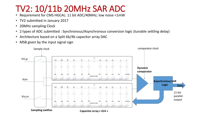
TV2: 10/11b 20MHz SAR ADC TV2: 10/11b 20MHz SAR ADC Requirement for CMS HGCAL: 11 bit ADC/40MHz; low noise <1mW TV2 submitted in January 2017 20MHz sampling Clock 2 types of ADC submitted : Synchronous/Asynchronous conversion logic (tunable settling delay) Architecture based on a Split 6b/4b capacitor array DAC MSB given by the input signal sign
TV2: SAR ADC tests TV2: SAR ADC tests Maximum sampling frequency: 15MHz, but 10MHz achieve better results DC characterization: INL, DNL, capa network Many parameters to be explored: delay, reference voltages, dynamic performance Channel 1, async version, no bootstrap, @ 10 MHz
HGROC: 11 HGROC: 11- -bit SAR ADC bit SAR ADC HGROC chip for CMOS HGCAL Submitted in July 2017 Based on TV2 architecture Improved digital 40MHz sampling Clock expected Asynchronous logic 2 capacitor array architectures
600um 175um
PLL PLL 320MHz clock input (LpGBT fast command clock, adjustable phase) 1,28GHz VCO frequency CLPS receiver - Submitted and used, not really tested apart CLPS driver - Driving current: 0,5 to 4 mA, step 0,5mA - Pre-emphasis: 0,5 to 4 mA, step 0,5 mA, pulse width 200, 300, 400 ps - Submitted, reception by November Specification description Value Vcm (common voltage) 0,6 V Vdiff (differential voltage) 100 to 200 mV Pre-emphasis current 0,5 to 4 mA Termination load 100
Clk=640MHz; Cp=0 1p 5p 10p; driver strength=2mA; Pre-Emphasis strength=1mA, pulse width=20%
Clk=640MHz; Cp=10p; driver strength=2mA; Pre-Emphasis strength=0,5 to 4mA, pulse width=20%