Data Link and Physical Layer Functions in Computer Networking
Explore the functions of the data link and physical layers in computer networking. Learn about packaging data, error detection, addressing, flow control, transmission of bits, encoding, configuration, synchronization, topologies, and more.

Download Presentation

Please find below an Image/Link to download the presentation.
The content on the website is provided AS IS for your information and personal use only. It may not be sold, licensed, or shared on other websites without obtaining consent from the author. If you encounter any issues during the download, it is possible that the publisher has removed the file from their server.
You are allowed to download the files provided on this website for personal or commercial use, subject to the condition that they are used lawfully. All files are the property of their respective owners.
The content on the website is provided AS IS for your information and personal use only. It may not be sold, licensed, or shared on other websites without obtaining consent from the author.
E N D
Presentation Transcript
OSI MODEL 3 Data link & Physical Layer - Mona eldrnawi - ID Student : 3749
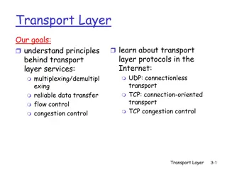
EXPLAIN THE FUNCTION OF DATA LINK & physical LAYER 01 FUNCTIONS OF DATA LINK
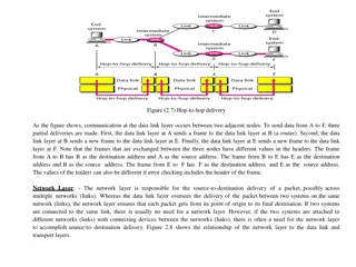
Data link Layer Functions The data link layer, is concerned with packaging data into frames and transmitting those frames on the network, performing error detection/ correction, uniquely identifying network devices with an address, and handling flow control. These processes are collectively referred to as data-link control (DLC).
Explain the functions of data link& physical layer 01 THE FUNCTIONS OF PHYSICAL LAYER
The functions of physical layer The physical layer, is concerned with the transmission of bits on the network along with the physical and electrical characteristics of the network. Representation of Bits: Data in this layer consists of stream of bits. The bits must be encoded into signals for transmission. It defines the type of encoding i.e. how 0's and 1's are changed to signal. Line Configuration:This layer connects devices with the medium: Point to Point configuration and Multipoint configuration. Data Rate: This layer defines the rate of transmission which is the number of bits per second. Topologies:Devices must be connected using the following topologies: Mesh, Star, Ring and Bus. Synchronization: It deals with the synchronization of the transmitter and receiver. The sender and receiver are synchronized at bit level. Transmission Modes: Physical Layer defines the direction of transmission between two devices: Simplex, Half Duplex, Full Duplex. Interface: The physical layer defines the transmission interface between devices and transmission medium. Bandwidth usage: Deals with baseband and broadband transmission.
Identify the purpose of each sub layer 02 THE PURPOSE OF Each sub LAYER
Purpose of Each sub layer Controlling access to media Transmitting bits across the local media Performing error detection on received frames Exchanging frames between nodes over physical network media o o o o
List & describe the components of Data link layer 03 COMPONENTS OF DATA LINK LAYER
Media Access Control (MAC) Characteristics of the Media Access Control (MAC) sublayer include the following: Physical addressing: A common example of a Layer 2 address is a MAC address, which is a 48-bit address assigned to a device s network interface card (NIC). The address is commonly written in hexadecimal notation. The first 24 bits of the 48-bit address are collectively referred to as the vendor code. Method of transmitting on the media: With several devices connected to a network, there needs to be some strategy for determining when a device is allowed to transmit on the media. Otherwise, multiple devices might transmit at the same time, and interfere with one another s transmissions. Logical topology: Layer 2 devices view a network as a logical topology. Examples of a logical topology include bus and ring topologies.
Logical Link Control (LLC) Characteristics of the Logical Link Control (LLC) sublayer include the following: Connection services: When a device on a network receives a message from another device on the network, that recipient device can provide feedback to the sender in the form of an acknowledgment message. The two main functions provided by these acknowledgment messages are as follows: - Flow control: Limits the amount of data a sender can send at one time; this prevents the receiver from being overwhelmed with too much information. - Error control: Allows the recipient of data to let the sender know whether the expected data frame was not received or whether it was received but is corrupted. The recipient determines whether the data frame is corrupted by mathematically calculating a checksum of the data received. If the calculated checksum does not match the checksum received with the data frame, the recipient of the data draws the conclusion that the data frame is corrupted and can then notify the sender via an acknowledgment message.
Logical Link Control (LLC) Characteristics of the Logical Link Control (LLC) sublayer include the following: Synchronizing transmissions: Senders and receivers of data frames need to coordinate when a data frame is being transmitted and should be received. Three methods of performing this synchronization are as follows: - Isochronous: With isochronous transmission, network devices look to a common device in the network as a clock source, which creates fixed-length time slots. Network devices can determine how much free space, if any, is available within a time slot and insert data into an available time slot. A time slot can accommodate more than one data frame. Isochronous transmission does not need to provide clocking at the beginning of a data string (as does synchronous transmission) or for every data frame (as does asynchronous transmission). As a result, isochronous transmission uses little overhead when compared to asynchronous or synchronous transmission methods. - Asynchronous: With asynchronous transmission, network devices reference their own internal clocks, and network devices do not need to synchronize their clocks. Instead, the sender places a start bit at the beginning of each data frame and a stop bit at the end of each data frame. These start and stop bits tell the receiver when to monitor the medium for the presence of bits. An additional bit, called the parity bit , might also be added to the end of each byte in a frame to detect an error in the frame.
Logical Link Control (LLC) Characteristics of the Logical Link Control (LLC) sublayer include the following: - Synchronous: With synchronous transmission, two network devices that want to communicate between themselves must agree on a clocking method to indicate the beginning and ending of data frames. One approach to providing this clocking is to use a separate communications channel over which a clock signal is sent. Another approach relies on specific bit combinations or control characters to indicate the beginning of a frame or a byte of data. Like asynchronous transmissions, synchronous transmissions can perform error detection. However, rather than using parity bits, synchronous communication runs a mathematical algorithm on the data to create a cyclic redundancy check (CRC). If both the sender and the receiver calculate the same CRC value for the same chunk of data, the receiver can conclude that the data was not corrupted during transmission.
04 Purpose & Characteristics of ethernet MAC Describe the purpose and characteristics of the ethernet MAC address (Data Network)
The purpose and charcteristics of the ethernet MAC address I. Multiplexing strategy: Multiplexing allows multiple communications sessions to share the same physical medium. Cable TV, as previously mentioned, allows you to receive multiple channels over a single physical medium (for ex-ample, a coaxial cable plugged into the back of your television). Here are some of the more common approaches to multiplexing: I. Time-division multiplexing (TDM): TDM supports different communication sessions (for example, different telephone conversations in a telephony network) on the same physical medium by causing the sessions to take turns. For a brief period of time, defined as a time slot, data from the first session will be sent, followed by data from the second session. This continues until all sessions have had a turn, and the process repeats itself. II. Statistical time-division multiplexing (StatTDM): A downside to TDM is that each communication session receives its own time slot, even if one of the sessions does not have any data to transmit at the moment. To make a more efficient use of available bandwidth, StatTDM dynamically assigns time slots to communications sessions on an as-needed basis. III. Frequency-division multiplexing (FDM): FDM divides a medium s frequency range into channels, and different communication sessions transmit their data over different channels. As previously described, this approach to bandwidth usage is called broadband. II. Examples of devices defined by physical layer standards include hubs, wireless access points, and network cabling.


")
")
")
")