Data Link and Physical Layers in Networking
Explore the concepts of Data Link and Physical Layers, including services, terminology, analogy, and services provided. Learn about link layer protocols, framing, reliability, flow control, error detection, and correction in high-performance networking systems.

Uploaded on | 3 Views
Download Presentation

Please find below an Image/Link to download the presentation.
The content on the website is provided AS IS for your information and personal use only. It may not be sold, licensed, or shared on other websites without obtaining consent from the author. If you encounter any issues during the download, it is possible that the publisher has removed the file from their server.
You are allowed to download the files provided on this website for personal or commercial use, subject to the condition that they are used lawfully. All files are the property of their respective owners.
The content on the website is provided AS IS for your information and personal use only. It may not be sold, licensed, or shared on other websites without obtaining consent from the author.
E N D
Presentation Transcript
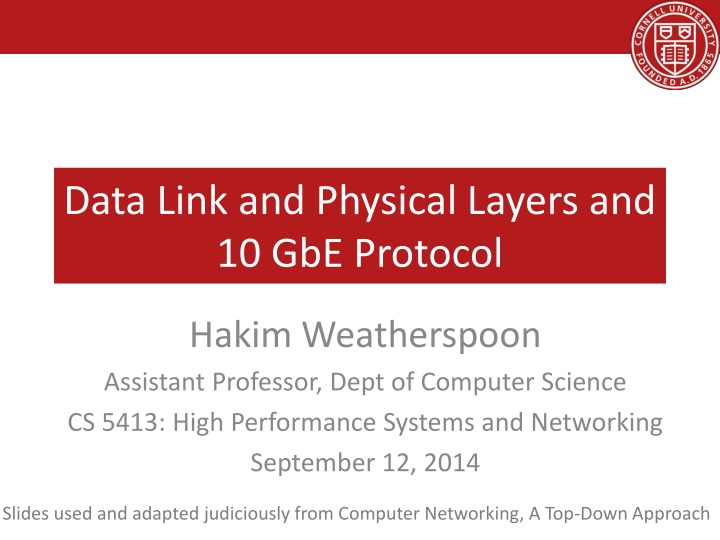
Data Link and Physical Layers and 10 GbE Protocol Hakim Weatherspoon Assistant Professor, Dept of Computer Science CS 5413: High Performance Systems and Networking September 12, 2014 Slides used and adapted judiciously from Computer Networking, A Top-Down Approach
Goals for Today Link Layer and Physical Layer Abstraction / services Switches and Local Area Networks Addressing, ARP (address resolution protocol) Ethernet Ethernet Switch Multiple Access Protocols Data Center Network 10GbE (10 Gigabit Ethernet) Backup Slides Virtual Local Area Networks (VLAN) Multiple Access Protocols Putting it all together: A day and a life of a web request
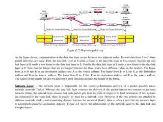
Link Layer terminology: hosts and routers: nodes communication channels that connect adjacent nodes along communication path: links wired links wireless links LANs layer-2 packet: frame, encapsulates datagram global ISP data-link layer has responsibility of transferring datagram from one node to physically adjacent node over a link
Link Layer transportation analogy: trip from Princeton to Lausanne limo: Princeton to JFK plane: JFK to Geneva train: Geneva to Lausanne tourist = datagram transport segment = communication link transportation mode = link layer protocol travel agent = routing algorithm datagram transferred by different link protocols over different links: e.g., Ethernet on first link, frame relay on intermediate links, 802.11 on last link each link protocol provides different services e.g., may or may not provide rdt over link
Link Layer Services framing, link access: encapsulate datagram into frame, adding header, trailer channel access if shared medium MAC addresses used in frame headers to identify source, dest different from IP address! reliable delivery between adjacent nodes we learned how to do this already (chapter 3)! seldom used on low bit-error link (fiber, some twisted pair) wireless links: high error rates Q: why both link-level and end-end reliability?
Link Layer Services flow control: pacing between adjacent sending and receiving nodes error detection: errors caused by signal attenuation, noise. receiver detects presence of errors: signals sender for retransmission or drops frame error correction: receiver identifies and corrects bit error(s) without resorting to retransmission half-duplex and full-duplex with half duplex, nodes at both ends of link can transmit, but not at same time
Link Layer Where is the link layer implemented? in each and every host link layer implemented in adaptor (aka network interface card NIC) or on a chip Ethernet card, 802.11 card; Ethernet chipset implements link, physical layer attaches into host s system buses combination of hardware, software, firmware application transport network link cpu memory host bus (e.g., PCI) controller link physical physical transmission network adapter card
Link Layer Adapters communicating datagram datagram controller controller receiving host sending host datagram frame receiving side looks for errors, rdt, flow control, etc extracts datagram, passes to upper layer at receiving side sending side: encapsulates datagram in frame adds error checking bits, rdt, flow control, etc.
Goals for Today Link Layer and Physical Layer Abstraction / services Switches and Local Area Networks Addressing, ARP (address resolution protocol) Ethernet Ethernet switch Multiple Access Protocols Data Center Network 10GbE (10 Gigabit Ethernet) Backup Slides Virtual Local Area Networks (VLAN) Multiple Access Protocols Putting it all together: A day and a life of a web request
Switches and Local Area Networks MAC (medium access control) addresses and ARP (address resolution protocol) 32-bit IP address: network-layer address for interface used for layer 3 (network layer) forwarding MAC (or LAN or physical or Ethernet) address: function: used locally to get frame from one interface to another physically-connected interface (same network, in IP-addressing sense) 48 bit MAC address (for most LANs) burned in NIC ROM, also sometimes software settable e.g.: 1A-2F-BB-76-09-AD hexadecimal (base 16) notation (each number represents 4 bits)
Switches and Local Area Networks LAN (MAC) addresses and ARP each adapter on LAN has unique LAN address 1A-2F-BB-76-09-AD LAN (wired or wireless) adapter 71-65-F7-2B-08-53 58-23-D7-FA-20-B0 0C-C4-11-6F-E3-98
Switches and Local Area Networks LAN (MAC) addresses and ARP MAC address allocation administered by IEEE manufacturer buys portion of MAC address space (to assure uniqueness) analogy: MAC address: like Social Security Number IP address: like postal address MAC flat address portability can move LAN card from one LAN to another IP hierarchical address not portable address depends on IP subnet to which node is attached
Switches and Local Area Networks LAN (MAC) addresses and ARP: Address Resolution Protocol Question: how to determine interface s MAC address, knowing its IP address? ARP table: each IP node (host, router) on LAN has table IP/MAC address mappings for some LAN nodes: < IP address; MAC address; TTL> TTL (Time To Live): time after which address mapping will be forgotten (typically 20 min) 137.196.7.78 1A-2F-BB-76-09-AD 137.196.7.23 137.196.7.14 LAN 71-65-F7-2B-08-53 58-23-D7-FA-20-B0 0C-C4-11-6F-E3-98 137.196.7.88
Switches and Local Area Networks ARP: Address Resolution Protocol; Same LAN A wants to send datagram to B B s MAC address not in A s ARP table. A broadcasts ARP query packet, containing B's IP address dest MAC address = FF-FF-FF-FF-FF-FF all nodes on LAN receive ARP query B receives ARP packet, replies to A with its (B's) MAC address frame sent to A s MAC address (unicast) A caches (saves) IP-to- MAC address pair in its ARP table until information becomes old (times out) soft state: information that times out (goes away) unless refreshed ARP is plug-and-play : nodes create their ARP tables without intervention from net administrator
Switches and Local Area Networks ARP: Address Resolution Protocol; different LAN walkthrough: send datagram from A to B via R focus on addressing at IP (datagram) and MAC layer (frame) assume A knows B s IP address assume A knows IP address of first hop router, R (how?) assume A knows R s MAC address (how?) B A R 111.111.111.111 74-29-9C-E8-FF-55 222.222.222.222 49-BD-D2-C7-56-2A 222.222.222.220 1A-23-F9-CD-06-9B 111.111.111.110 E6-E9-00-17-BB-4B 222.222.222.221 88-B2-2F-54-1A-0F 111.111.111.112 CC-49-DE-D0-AB-7D
Switches and Local Area Networks ARP: Address Resolution Protocol; different LAN A creates IP datagram with IP source A, destination B A creates link-layer frame with R's MAC address as dest, frame contains A-to-B IP datagram MAC src: 74-29-9C-E8-FF-55 MAC dest: E6-E9-00-17-BB-4B IP src: 111.111.111.111 IP dest: 222.222.222.222 IP Eth Phy B A R 111.111.111.111 74-29-9C-E8-FF-55 222.222.222.222 49-BD-D2-C7-56-2A 222.222.222.220 1A-23-F9-CD-06-9B 111.111.111.110 E6-E9-00-17-BB-4B 222.222.222.221 88-B2-2F-54-1A-0F 111.111.111.112 CC-49-DE-D0-AB-7D
Switches and Local Area Networks ARP: Address Resolution Protocol; different LAN frame sent from A to R frame received at R, datagram removed, passed up to IP MAC src: 74-29-9C-E8-FF-55 MAC dest: E6-E9-00-17-BB-4B IP src: 111.111.111.111 IP dest: 222.222.222.222 IP src: 111.111.111.111 IP dest: 222.222.222.222 IP Eth Phy IP Eth Phy B A R 111.111.111.111 74-29-9C-E8-FF-55 222.222.222.222 49-BD-D2-C7-56-2A 222.222.222.220 1A-23-F9-CD-06-9B 111.111.111.110 E6-E9-00-17-BB-4B 222.222.222.221 88-B2-2F-54-1A-0F 111.111.111.112 CC-49-DE-D0-AB-7D
Switches and Local Area Networks ARP: Address Resolution Protocol; different LAN R forwards datagram with IP source A, destination B R creates link-layer frame with B's MAC address as dest, frame contains A-to-B IP datagram MAC src: 1A-23-F9-CD-06-9B MAC dest: 49-BD-D2-C7-56-2A IP src: 111.111.111.111 IP dest: 222.222.222.222 IP Eth Phy IP Eth Phy B A R 111.111.111.111 74-29-9C-E8-FF-55 222.222.222.222 49-BD-D2-C7-56-2A 222.222.222.220 1A-23-F9-CD-06-9B 111.111.111.110 E6-E9-00-17-BB-4B 222.222.222.221 88-B2-2F-54-1A-0F 111.111.111.112 CC-49-DE-D0-AB-7D
Switches and Local Area Networks ARP: Address Resolution Protocol; different LAN R forwards datagram with IP source A, destination B R creates link-layer frame with B's MAC address as dest, frame contains A-to-B IP datagram MAC src: 1A-23-F9-CD-06-9B MAC dest: 49-BD-D2-C7-56-2A IP src: 111.111.111.111 IP dest: 222.222.222.222 IP Eth Phy IP Eth Phy B A R 111.111.111.111 74-29-9C-E8-FF-55 222.222.222.222 49-BD-D2-C7-56-2A 222.222.222.220 1A-23-F9-CD-06-9B 111.111.111.110 E6-E9-00-17-BB-4B 222.222.222.221 88-B2-2F-54-1A-0F 111.111.111.112 CC-49-DE-D0-AB-7D
Switches and Local Area Networks ARP: Address Resolution Protocol; different LAN R forwards datagram with IP source A, destination B R creates link-layer frame with B's MAC address as dest, frame contains A-to-B IP datagram MAC src: 1A-23-F9-CD-06-9B MAC dest: 49-BD-D2-C7-56-2A IP src: 111.111.111.111 IP dest: 222.222.222.222 IP Eth Phy B A R 111.111.111.111 74-29-9C-E8-FF-55 222.222.222.222 49-BD-D2-C7-56-2A 222.222.222.220 1A-23-F9-CD-06-9B 111.111.111.110 E6-E9-00-17-BB-4B 222.222.222.221 88-B2-2F-54-1A-0F 111.111.111.112 CC-49-DE-D0-AB-7D
Goals for Today Link Layer and Physical Layer Abstraction / services Switches and Local Area Networks Addressing, ARP (address resolution protocol) Ethernet Ethernet switch Multiple Access Protocols Data Center Network 10GbE (10 Gigabit Ethernet) Backup Slides Virtual Local Area Networks (VLAN) Multiple Access Protocols Putting it all together: A day and a life of a web request
Link and Physical Layer: Ethernet dominant wired LAN technology: cheap $20 for NIC first widely used LAN technology simpler, cheaper than token LANs and ATM kept up with speed race: 10 Mbps 10 Gbps Metcalfe s Ethernet sketch
Link and Physical Layer: Ethernet Ethernet Physical Topologies bus: popular through mid 90s all nodes in same collision domain (can collide with each other) star: prevails today active switch in center each spoke runs a (separate) Ethernet protocol (nodes do not collide with each other) switch star bus: coaxial cable
Link and Physical Layer: Ethernet Ethernet frame structure/format sending adapter encapsulates IP datagram (or other network layer protocol packet) in Ethernet frame dest. address address preamble type data source CRC (payload) preamble: 7 bytes with pattern 10101010 followed by one byte with pattern 10101011 used to synchronize receiver, sender clock rates
Link and Physical Layer: Ethernet Ethernet frame structure/format addresses: 6 byte source, destination MAC addresses if adapter receives frame with matching destination address, or with broadcast address (e.g. ARP packet), it passes data in frame to network layer protocol otherwise, adapter discards frame type: indicates higher layer protocol (mostly IP but others possible, e.g., Novell IPX, AppleTalk) CRC: cyclic redundancy check at receiver error detected: frame is dropped type data dest. address source address CRC preamble (payload)
Link and Physical Layer: Ethernet Ethernet service abstraction and implementation connectionless: no handshaking between sending and receiving NICs unreliable: receiving NIC doesnt send acks or nacks to sending NIC data in dropped frames recovered only if initial sender uses higher layer rdt (e.g., TCP), otherwise dropped data lost Ethernet s MAC protocol: unslotted CSMA/CD wth binary backoff
Link and Physical Layer: Ethernet IEEE 802.3 Ethernet Standards: link & physical layers many different Ethernet standards common MAC protocol and frame format different speeds: 2 Mbps, 10 Mbps, 100 Mbps, 1Gbps, 10G bps different physical layer media: fiber, cable MAC protocol and frame format application transport network link physical 100BASE-T2 100BASE-FX 100BASE-TX 100BASE-BX 100BASE-SX 100BASE-T4 fiber physical layer copper (twister pair) physical layer
Goals for Today Link Layer and Physical Layer Abstraction / services Switches and Local Area Networks Addressing, ARP (address resolution protocol) Ethernet Ethernet switch Multiple Access Protocols Data Center Network 10GbE (10 Gigabit Ethernet) Backup Slides Virtual Local Area Networks (VLAN) Multiple Access Protocols Putting it all together: A day and a life of a web request
Ethernet Switch link-layer device: takes an active role store, forward Ethernet frames examine incoming frame s MAC address, selectively forward frame to one-or-more outgoing links when frame is to be forwarded on segment, uses CSMA/CD to access segment transparent hosts are unaware of presence of switches plug-and-play, self-learning switches do not need to be configured
Ethernet Switch Switch: Multiple Simultaneous Transmission hosts have dedicated, direct connection to switch switches buffer packets Ethernet protocol used on each incoming link, but no collisions; full duplex each link is its own collision domain switching: A-to-A and B-to-B can transmit simultaneously, without collisions A B C 1 2 6 4 5 3 C B A switch with six interfaces (1,2,3,4,5,6)
Ethernet Switch Switch Forwarding Table Q: how does switch know A reachable via interface 4, B reachable via interface 5? A: each switch has a switch table, each entry: (MAC address of host, interface to reach host, time stamp) looks like a routing table! A B C 1 2 6 4 5 3 C B A Q: how are entries created, maintained in switch table? something like a routing protocol? switch with six interfaces (1,2,3,4,5,6)
Ethernet Switch Source: A Dest: A Switch: Self-learning A A A switch learns which hosts can be reached through which interfaces when frame received, switch learns location of sender: incoming LAN segment records sender/location pair in switch table B C 1 2 6 4 5 3 C B A MAC addr interface TTL Switch table (initially empty) 60 1 A
Ethernet Switch Ethernet Switch Switch: Frame filtering/forwarding When frame received at switch: 1. record incoming link, MAC address of sending host 2. index switch table using MAC destination address 3. ifentry found for destination then { ifdestination on segment from which frame arrived then drop frame else forward frame on interface indicated by entry } else flood /* forward on all interfaces except arriving interface */
Ethernet Switch Source: A Dest: A Example: Self-learning, forwarding A A A frame destination, A , locaton unknown:flood B C 1 destination A location known: selectively send on just one link 2 6 A A A A A A A A A A 4 5 3 C B A A A MAC addr interface TTL switch table (initially empty) 60 60 1 4 A A
Ethernet Switch Interconnecting Switches switches can be connected together S4 S1 S3 S2 A F I D C B H G E Q: sending from A to G - how does S1 know to forward frame destined to F via S4 and S3? A: self learning! (works exactly the same as in single-switch case!)
Ethernet Switch Institutional Network mail server to external network web server router IP subnet
Ethernet Switch Switches vs Routers application transport network link physical both are store-and-forward: routers: network-layer devices (examine network- layer headers) switches: link-layer devices (examine link-layer headers) datagram frame link frame physical switch network link physical datagram frame both have forwarding tables: routers: compute tables using routing algorithms, IP addresses switches: learn forwarding table using flooding, learning, MAC addresses application transport network link physical
Goals for Today Link Layer and Physical Layer Abstraction / services Switches and Local Area Networks Addressing, ARP (address resolution protocol) Ethernet Ethernet switch Multiple Access Protocols Data Center Network 10GbE (10 Gigabit Ethernet) Backup Slides Virtual Local Area Networks (VLAN) Multiple Access Protocols Putting it all together: A day and a life of a web request
Multiple Access Links, Protocols two types of links : point-to-point PPP for dial-up access point-to-point link between Ethernet switch, host broadcast (shared wire or medium) old-fashioned Ethernet upstream HFC 802.11 wireless LAN shared RF (e.g., 802.11 WiFi) shared RF (satellite) shared wire (e.g., cabled Ethernet) humans at a cocktail party (shared air, acoustical)
Multiple Access Links, Protocols MAC Protocols: Taxonomy three broad classes: channel partitioning divide channel into smaller pieces (time slots, frequency, code) allocate piece to node for exclusive use random access channel not divided, allow collisions recover from collisions taking turns nodes take turns, but nodes with more to send can take longer turns
Multiple Access Links, Protocols MAC Protocols: Tradeoffs channel partitioning MAC protocols: share channel efficiently and fairly at high load inefficient at low load: delay in channel access, 1/N bandwidth allocated even if only 1 active node! random access MAC protocols efficient at low load: single node can fully utilize channel high load: collision overhead taking turns protocols look for best of both worlds!
Multiple Access Links, Protocols MAC Protocols channel partitioning, by time, frequency or code Time Division, Frequency Division random access (dynamic), ALOHA, S-ALOHA, CSMA, CSMA/CD carrier sensing: easy in some technologies (wire), hard in others (wireless) CSMA/CD used in Ethernet CSMA/CA used in 802.11 taking turns polling from central site, token passing bluetooth, FDDI, token ring
Goals for Today Link Layer and Physical Layer Abstraction / services Switches and Local Area Networks Addressing, ARP (address resolution protocol) Ethernet Ethernet switch Multiple Access Protocols Data Center Network 10GbE (10 Gigabit Ethernet) Backup Slides Virtual Local Area Networks (VLAN) Multiple Access Protocols Putting it all together: A day and a life of a web request
10GbE (10 gigabit Ethernet) Application Data Transport L3 Hdr Data Network L2 Hdr L3 Hdr Data Data Link Preamble Eth Hdr L2 Hdr L3 Hdr Data CRC Gap Physical 64/66b PCS Encode Encode 2 bit syncheader Idle characters (/I/) 64 bit 10.3125 Gigabits /S/ /S/ /D/ /D/ /D/ /D/ /D/ /D/ /D/ /D/ /T/ /T/ /E/ /E/ Decode 16 bit Scrambler Scrambler Descrambler Gearbox Gearbox Blocksync PMA PMA 011010010110100101101001011010010110100101101001011010010110100101101 PMD 3/19/2025 SoNIC 46
10GbE (10 gigabit Ethernet) Block Payload Sync 0 8 16 24 32 40 48 56 65 Application Application Data Block 01 D0 D1 D2 D3 D4 D5 D6 D7 Block Type Transport Transport /E/ 10 0x1e C0 C1 C2 C3 C4 C5 C6 C7 10 0x33 C0 C1 C2 C3 D5 D6 D7 /S/ Network Network 10 0x78 D1 D2 D3 D4 D5 D6 D7 10 0x87 C1 C2 C3 C4 C5 C6 C7 Data Link Data Link 10 0x99 D0 C2 C3 C4 C5 C6 C7 10 10 0xaa 0xb4 D0 D0 D1 D1 C3 C4 C4 C5 C5 C6 C6 C7 C7 Physical Physical D2 /T/ 10 0xcc D0 D1 D2 D3 C5 C6 C7 64/66b PCS 10 0xd2 D0 D1 D2 D3 D4 C6 C7 PMA 10 0xe1 D0 D1 D2 D3 D4 D5 C7 10 0xff D0 D1 D2 D3 D4 D5 D6 PMD Ethernet Frame Gap Start of Frame block /S/ End of Frame block /T/ /S/ /D/ /D/ /D/ /D/ /T/ /E/ Idle block /E/ SoNIC 47 Data block /D/
10GbE (10 gigabit Ethernet) SoNIC: Software network interface card Hyper-fidelity network measurements Interpacket gap, spacing, arrival time, IPG Application Transport Packet i Packet i+1 Network IPD Data Link Important metric for network measurements Can be improved with access to the PHY Generation Physical Increasing Throughput Detecting timing channel Packet Capture Packet Estimating bandwidth Characterization 3/19/2025 48
10GbE (10 gigabit Ethernet) SoNIC: Software network interface card Hyper-fidelity network measurements Valuable information: Idle characters IPG Application Transport Packet i Packet i+1 Network IPD Data Link Can provide precise timing base for control Each bit is ~97 ps wide Physical 3/19/2025 49
10GbE (10 gigabit Ethernet) SoNIC: Software network interface card Hyper-fidelity network measurements Valuable information: Idle characters 12 /I/s = 100bits = 9.7ns IPG Application Transport Packet i Packet i+1 Network One Idle character (/I/) = 7~8 bits Data Link Can provide precise timing base for control Each bit is ~97 ps wide Generation Physical Detecting timing channel Packet Capture Packet 3/19/2025 50
Goals for Today Link Layer and Physical Layer Abstraction / services Switches and Local Area Networks Addressing, ARP (address resolution protocol) Ethernet Ethernet switch Multiple Access Protocols Data Center Network 10GbE (10 Gigabit Ethernet) Backup Slides Virtual Local Area Networks (VLAN) Multiple Access Protocols Putting it all together: A day and a life of a web request
Perspective principles behind data link layer services: link layer addressing sharing a broadcast channel: multiple access error detection, correction instantiation and implementation of various link layer technologies Ethernet switched LANS


")
")
")
")
")