Data Link Layer: CRC and Polynomials in Computer Networks
Explore the concept of Cyclic Redundancy Check (CRC) and how it uses polynomial codes to detect errors in data transmission. Learn how CRC polynomial codes work, how they are transmitted, and how they ensure data integrity in networking.

Download Presentation

Please find below an Image/Link to download the presentation.
The content on the website is provided AS IS for your information and personal use only. It may not be sold, licensed, or shared on other websites without obtaining consent from the author. If you encounter any issues during the download, it is possible that the publisher has removed the file from their server.
You are allowed to download the files provided on this website for personal or commercial use, subject to the condition that they are used lawfully. All files are the property of their respective owners.
The content on the website is provided AS IS for your information and personal use only. It may not be sold, licensed, or shared on other websites without obtaining consent from the author.
E N D
Presentation Transcript
Computer Networks Lecture 5: Data Link layer Part II Based on slides from D. Choffnes Northeastern U. and P. Gill from StonyBrook University Revised Autumn 2015 by S. Laki
Cyclic Redundancy Check (CRC) 2 Uses field theory to compute a semi-unique value for a given message Much better performance than previous approaches Fixed size overhead per frame (usually 32-bits) Quick to implement in hardware Only 1 in 232 chance of missing an error with 32-bit CRC
CRC (Cyclic Redundancy Check) Polynomial code Treating bit strings as representations of polynomials with coefficients of 0 and 1. CRC Add k bits of redundant data to an n-bit message. Represent n-bit message as an n-1 degree polynomial; e.g., MSG=10011010 corresponds to M(x) = x7+ x4 + x3 + x1. Let k be the degree of some divisor polynomial G(x); e.g., G(x) = x3+ x2 + 1. Generator polynomial Agreed upon it in advance
CRC Transmit polynomial P(x) that is evenly divisible by G(x), and receive polynomial P(x) + E(x); E(x)=0 implies no errors. Recipient divides (P(x) + E(x)) by G(x); the remainder will be zero in only two cases: E(x) was zero (i.e. there was no error), or E(x) is exactly divisible by C(x). Choose G(x) to make second case extremely rare.
CRC summary 5 Source: Dr. Lukovszki Tam s
A basic example with numbers Make all legal messages divisible by 3 If you want to send 10 First multiply by 4 to get 40 Now add 2 to make it divisible by 3 = 42 When the data is received .. Divide by 3, if there is no remainder there is no error If no error, divide by 4 to get sent message If we receive 43, 44, 41, 40, then error 45 would not be recognized as an error
Mod 2 arithmetic Operations are done modulo 2 1111 +1010 ===== 0101 11001 x 101 ===== 11001 + 11001 ========= 1111101
A basic example with polynomials Sender: multiply M(x) = x7+ x4 + x3 + x1by xk; for our example, we get x10 + x7 + x6+ x4(10011010000); divide result by C(x) (1101); 11111001 10011010000 Message 1101 1001 1101 1000 1101 1011 1101 1100 1101 1000 1101 101 Remainder Generator 1101 Send 10011010000 + 101 = 10011010101, since this must be exactly divisible by C(x);
Further properties Want to ensure that G(x) does not divide evenly into polynomial E(x). All single-bit errors, as long as the xkand x0 terms have non-zero coefficients. All double-bit errors, as long as G(x) has a factor with at least three terms. Any odd number of errors, as long as G(x) contains the factor (x + 1). Any burst error (i.e sequence of consecutive errored bits) for which the length of the burst is less than k bits. Most burst errors of larger than k bits can also be detected.
Even Parity Actually consists of using x+1 polynomial Given message 0111, multiply by x to get 01110 Now divide by x+1=11 0101 11 01110 11 0010 11 1=remainder Message = 01110+1=01111 even parity
Common polynomials for C(x): CRC C(x) CRC-8 x8+x2+x1+1 CRC-10 x10+x9+x5+x4+x1+1 CRC-12 x12+x11+x3+x2+x1+1 CRC-16 x16+x15+x2+1 CRC-CCITT x16+x12+x5+1 CRC-32 x32+x26+x23+x22+x16+x12+x11+x10+x8+x7+x5+x4+x2+x+1
Error control Error Control Strategies Error Correcting codes (Forward Error Correction (FEC)) Error detection and retransmission Automatic Repeat Request (ARQ)
Error control Objectives Error detection with correction Forward error correction without correction -> e.g. drop a frame Backward error correction The erroneous frame needs to be retransmitted Error correction without error detection e.g. in voice transmission
Should We Error Check in the Data Link? 14 Recall the End-to-End Argument Cons: Error free transmission cannot be guaranteed Not all applications want this functionality Error checking adds CPU and packet size overhead Error recovery requires buffering Pros: Potentially better performance than app-level error checking Data link error checking in practice Most useful over lossy links Wifi, cellular, satellite
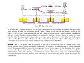
Backward error correction Error detection at the receiver side The sender retransmits a frame until it received by the other side correctly. Packets Network Layer Network Layer from from_ _upper upper(p) (p) to to_ _upper upper(p) (p) Frames Data Link Layer Data Link Layer from from_ _lower lower(p) (p) to to_ _lower lower(p) (p) Physical Layer Bits
Elementary Data Link Protocols Simplex Stop-and-Wait Protocol Alternate Bit Protocol Sliding Window Protocol
Simple Stop-and-Wait Protocol A sends a message to B A stops and waits for an answer from B Acknowledgement message (ACK) After receiving the message B sends an ACK back to the sender. A retransmits the message until it receives an ACK from B If the ACK arrived, the next message may be sent.
Simplex Stop-and-Wait Protocol Sender Receiver
Stop-and-Wait Diagram 22 Simple, but inefficient for long distance and high speed applications. We can use sliding-window technique to improve the efficiency.
Whats the problem? Packet loss ACK loss Usually
Alternating Bit Protocol (ABP) Let A be the sender B be the receiver A and B maintain internal one-bit counter A value that is 0 or 1 Each message from A to B contains a data part and a one-bit sequence number E.g. a value that is 0 or 1 After receiving A s message, B sends an ACK back to A which also contains a one-bit sequence number Retransmission until A receives an ACK from B with the same sequence number Then A complements its sequence number 0->1 or 1->0
Alternating Bit Protocol (ABP) Sender Receiver
Alternating Bit Protocol (ABP) A reliable data transport over a noisy channel Basic flow control The sender has to wait for the ACK from the receiver before sending the next message Automatic Repeat reQest (ARQ) protocol An acknowledgement marks that the new message has been delivered. allows the sender to tranmit the next frame.
Alternating Bit Protocol Two scenarios for ABP. (a) Normal case. (b) Abnormal case. The notation is (seq, ack, packet number). An asterisk indicates where a network layer accepts a packet.
ABP Channel utilization Utilization ( ) is the ratio of The time needed for the transmission of a frame (Tpacket) The time ellapsed until the next frame can be transmitted In the fig.: (Tpacket+ d + Tack+ d) Time Now: = Tpacket/ (Tpacket+ d + Tack+ d) If the propagation delay is large, the ABP is not efficient.
How to improve the efficency? The sender transmit frames continously one after another More frames are sent out, but not acknowledged. Pipeline technique Time Introduce sequence numbers
Sliding Window Protocols Similar to ABP but allow multiple frames to transmit Receiver has a buffer of W frames Sender can send up to W frames without receiving ACK Bidirectional Each outgoing frame contains a seq. number from 0 to 2n-1. So it fits in an n-bit field ABP uses n=1 Each ACK carries the sequence number of the next expected frame by the receiver
Sliding Window Protocols At the sender Sending window a set of sequence numbers corresponding to frames being under transmission (finite range of numbers) At the receiver Receiving window Sequence numbers for frames it is permitted to accept (finite range of numbers) The sender s and receiver s windows need not have tha same lower and upper bounds and even have the same size. The window size can be fixed or grow or shrink over the course of time as frames are sent and received
Sliding-Window Diagram 32 Need to buffer them in case of retransmission
Example Sliding-Window 33 RR3 means the receiver has received all frames up to frame 2 and is ready to receive frame 3. More spaces for future frames Have been delivered to upper layer
Sliding Window Protocols A sliding window of size 1, with a 3-bit sequence number. (a) Initially. (b) After the first frame has been sent. (c) After the first frame has been received. (d) After the first acknowledgement has been received.
Go-Back-N A sliding window protocol where the receiver s window size is fixed to 1, while the sender has window size > 0. After receiving a damaged frame Receiver discards all subsequent frames Sender retransmits the damaged frame and all its successors after the times out
Selective Repeat Receiver s window size is n ( n >1 ) At most n frames can be buffered Receiver stores all the correct frames following the bad one The sender retransmits only the bad frame not all its successors
Communication channels and piggybacking Simplex Communication in one direction only Half-duplex Communication in both directions, but only one direction at a time, not simultaneously. Full-duplex Communication in both directions simultaneously The previous protocols assumed a simplex channel to the upper (network) layer and a (half-)duplex channel to the physical layer If we use duplex channel to the upper layers Transmitting data packet and acknowledgements in both directions separately Or using piggybacking The header of a data packet sent in the opposite direction carries the acknowledgement back to the other side widely applied in practice
Outline 41 Framing Error Checking and Reliability Media Access Control 802.3 Ethernet 802.11 Wifi
What is Media Access? 42 Ethernet and Wifi are both multi-access technologies Broadcast medium, shared by many hosts Simultaneous transmissions cause collisions This destroys the data Media Access Control (MAC) protocols are required Rules on how to share the medium Strategies for detecting, avoiding, and recovering from collisions
Strategies for Media Access 43 Channel partitioning Divide the resource into small pieces Allocate each piece to one host Example: Time Division Multi-Access (TDMA) cellular Example: Frequency Division Multi-Access (FDMA) cellular Taking turns Tightly coordinate shared access to avoid collisions Example: Token ring networks
Channel Partitioning Frequency Division Multiplexing E.g. a telephone trunk Time Division Multiplexing Are they good solutions? if data rates are fixed if the link utilization is good
Whats the problem? The number of senders is large continuously varying bursty traffic
Bursty traffic If there s huge difference between the peak rate and the mean (or average) rate In computer networks it is not rare peak rate/mean rate = 1000/1
Bursty traffic with Static Channel Allocation The capacity of the channels must be Either quite large to handle peak rates Waste of resources The mean rate is much less than the peak one Or based on the mean rate We need buffers/queues to store packets coming faster than the mean rate Queuing delays BUFFERS Incoming packets
Whats about delays? If there s no multiplexing A source has data rate of p bps The capacity of the link is C bps The delay is T Bursty traffic with static channel allocation Dividing the channel into N static subchannels With sending rate p/N bps and capacity C/N The delay is N T Static channel allocation increases the packet delays Because of the idle subchannels
Dynamic Channel Allocation in LANs and MANs 1. Station Model. N terminals/hosts The prob. of a frame being generated in t is t, where the arrival rate is . 2. Single Channel Assumption. All stations are equivalent A single channel is available for all communications 3. Collision Assumption. If two frames are transmitted simultaneously, they overlap in time which results a garbled signal This event is called collision 4. Continuous Time VS Slotted Time. 5. Carrier Sense VS No Carrier Sense.
Dynamic Channel Allocation in LANs and MANs 4. Continuous Time VS Slotted Time. Time Time 5. Carrier Sense VS No Carrier Sense.

")
")


:")


")
")
")