DC Offset Corrector in ADS54Jxx Devices
Learn about the DC offset corrector in ADS54Jxx devices, its impact on data streams, and how it helps reduce mismatch among interleaving cores by adjusting DC offsets. Discover how to control, bypass, or freeze the correction block for optimal performance in ADC systems.

Download Presentation

Please find below an Image/Link to download the presentation.
The content on the website is provided AS IS for your information and personal use only. It may not be sold, licensed, or shared on other websites without obtaining consent from the author. If you encounter any issues during the download, it is possible that the publisher has removed the file from their server.
You are allowed to download the files provided on this website for personal or commercial use, subject to the condition that they are used lawfully. All files are the property of their respective owners.
The content on the website is provided AS IS for your information and personal use only. It may not be sold, licensed, or shared on other websites without obtaining consent from the author.
E N D
Presentation Transcript
DC Offset corrector in ADS54Jxx Devices 25 Feb 2021
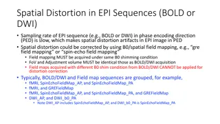
The DC offset Corrector in ADS54Jxx ADS54Jxx one channel DC offset Corr 250 Msps Data stream Core 1 DC offset Corr 250 Msps Data stream Analog input CHx Core 2 1 Gsps Data stream Interleaving Engine Buffer 250 Msps Data stream DC offset Corr Core 3 DC offset Corr 250 Msps Data stream Core 4
The DC offset Corrector in ADS54Jxx..contd In a 4-way interleaving ADC, the DC offset mismatch among interleaving cores causes the tones at fs/4, fs/2. Average offset of four cores appears at DC. To overcome this, the ADS54Jxx employs a DC offset corrector block at individual core level to bring the each core s offset to ideal mid-code value, thereby reducing the mismatch. DC offset corrector s implementation is shown below it can be left running(default), frozen or bypassed. When left running, the corrector continuously estimates and subtracts the average from data stream. When Frozen, it holds the last estimate, doesn t update the estimate but subtracts it from data stream. When disabled, it doesn t subtracts the estimate from data stream. - Input data stream (250 MSPS) 0 DC offset Estimator Output stream (250 MSPS) FREEZE OFFSET CORR 1 1. 2. DC offset corrector page address =6100h In this page, register address 0x68 controls the DC offset correction features. DISABLE OFFSET CORR DC offset corrector page [address= 0x6100; to be selected through JESD BANK PAGE select bits] bit 7 bit 6 bit 5 bit 4 bit 3 bit 2 bit 1 bit 0 Reg Address 0x68 FREEZE OFFSET CORR DC OFFSET CORR BW BYPASS OFFSET CORR ALWAYS WRITE 1 0
The DC offset Corrector in ADS54Jxx..contd DC Offset correction block is HPF filter which removes the DC content of incoming data stream. The DC offset correction block operates individually on interleaving ADC core s output. This results in removal of DC, fs/4, and fs/2 components from combined interleaved data. DC offset corrector block is enabled by default. DC offset corrector block has correction range of +/-15mV offset. If input signal falls on these frequencies, the offset corrector block can be either bypasses or frozen. Bypass DC offset correction block: The block can be bypassed on per channel basis. The Register settings to bypass the offset corrector block are described below. Bypassing DC correction block (Addr,val)=(0x4004,0x61); #Select Offset Corrector page (Addr,val)=(0x4003,0x00); (Addr,val)=(0x4002,0x00); (Addr,val)=(0x4001,0x00); (Addr,val)=(0x6068,0x06); #Bypass DC corrector for ch A (Addr,val)=(0x7068,0x06); #Bypass DC corrector for ch B When DC offset corrector is bypassed, offset mismatch among interleaving cores appear in interleaved output spectrum as spur at fs/4 and fs/2 frequency points. Amplitude of these spurs can be as big as -40dBFS.
The DC offset Corrector in ADS54Jxx..contd In order to avoid mismatch among interleaving cores appears as spur at fs/4 and fs/2, the offset corrector block can be allowed to estimate the internal mismatch with idle channel input and then be frozen. Since the corrector operated at individual core s level, it removes the internal DC offset too from interleaved output. Calibrating the internal DC offset mismatch and Freezing DC offset correction block: Remove any signal from analog inputs of channel being calibrated (i.e. idle channel input). Wait for 50-ms time to allow the offset corrector to estimate the internal mismatch. Freeze the offset corrector using following settings (the block can be frozen on per channel basis): Freezing DC correction block (Addr,val)=(0x4004,0x61); #Select Offset Corrector page (Addr,val)=(0x4003,0x00); (Addr,val)=(0x4002,0x00); (Addr,val)=(0x4001,0x00); (Addr,val)=(0x6068,0x82); #Freeze DC corrector for ch A (Addr,val)=(0x7068,0x82); #Freeze DC corrector for ch B When corrector is frozen it holds the last estimate of the mismatch and keeps subtracting it from output data. The spurs at DC, fs/4 and fs/2 due to internal DC offset are corrected to typically better than 80dBFS level. However, when temperature is changed, the level of spurs will change as the internal DC offset of individual ADC cores will change. Now the signal at the analog inputs can be applied. See the latest copy of ADS54J60 data sheet, section 9.1.4, for enabling loading of external estimates into the offset correction block.