Decode Logic and Control Overview
Discover the inner workings of decode logic and control in a processor, including instruction validation, register file operations, and operand decoding. Explore the process of handling instructions and executing conditional moves efficiently.

Download Presentation

Please find below an Image/Link to download the presentation.
The content on the website is provided AS IS for your information and personal use only. It may not be sold, licensed, or shared on other websites without obtaining consent from the author. If you encounter any issues during the download, it is possible that the publisher has removed the file from their server.
You are allowed to download the files provided on this website for personal or commercial use, subject to the condition that they are used lawfully. All files are the property of their respective owners.
The content on the website is provided AS IS for your information and personal use only. It may not be sold, licensed, or shared on other websites without obtaining consent from the author.
E N D
Presentation Transcript
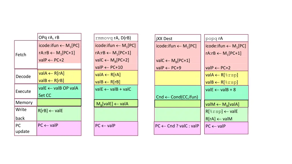
OPq rA, rB icode:ifun M1[PC] rA:rB M1[PC+1] valP PC+2 rmmovq rA, D(rB) icode:ifun M1[PC] rA:rB M1[PC+1] valC M8[PC+2] valP PC+10 valA R[rA] valB R[rB] valE valB + valC popq rA icode:ifun M1[PC] rA:rB M1[PC+1] jXX Dest icode:ifun M1[PC] Fetch valC M8[PC+1] valP PC+9 valP PC+2 valA R[%rsp] valB R[%rsp] valE valB + 8 valA R[rA] valB R[rB] valE valB OP valA Set CC Decode Execute Cnd Cond(CC,ifun) Memory Write M8[valE] valA valM M8[valA] R[%rsp] valE R[rA] valM PC valP R[rB] valE back PC update PC valP PC valP PC Cnd ? valC : valP
Fetch Logic icode ifun rA rB valC valP Control Logic Instr. Valid: Is this instruction valid? icode, ifun: Generate no-op if invalid address Need regids: Does this instruction have a register byte? Need valC: Does this instruction have a constant word? Need valC PC increment Instr valid Need regids icode ifun Split Align Byte 0 Bytes 1-9 Instruction memory imem_error PC
Decode Logic Register File Read ports A, B Write ports E, M Addresses are register IDs or 15 (0xF) (no access) Cnd valA valB valM valE A B M Register file E dstE dstM srcA srcB Control Logic srcA, srcB: read port addresses dstE, dstM: write port addresses Signals dstE dstM srcA srcB Cnd: Indicate whether or not to perform conditional move icode rA rB Computed in Execute stage
A Source OPq rA, rB valA R[rA] Decode Read operand A cmovXX rA, rB valA R[rA] Decode Read operand A int srcA = [ icode in {IOPQ, IRRMOVQ, IRMMOVQ, IPUSHQ}: rA; icode in {IPOPQ, IRET}: RRSP; 1 : RNONE; # Don't need register ]; rmmovq rA, D(rB) valA R[rA] Decode Read operand A popq rA valA R[%rsp] Decode Read stack pointer jXX Dest Decode No operand call Dest Decode No operand ret valA R[%rsp] Decode Read stack pointer
E Destination OPq rA, rB R[rB] valE Write-back Write back result cmovXX rA, rB Conditionally write back result R[rB] valE Write-back int dstE = [ rmmovq rA, D(rB) Write-back None icode in {IRRMOVQ} && Cnd: rB; popq rA icode in {IIRMOVQ, IOPQ} : rB; icode in {IPUSHQ, IPOPQ, ICALL, IRET}: RRSP; 1 : RNONE; # Don't write any register ]; R[%rsp] valE Write-back Update stack pointer jXX Dest Write-back None call Dest R[%rsp] valE Write-back Update stack pointer ret R[%rsp] valE Write-back Update stack pointer
Execute Logic Units ALU Cnd valE Implements 4 required functions Generates condition code values CC Register with 3 condition code bits cond Computes conditional jump/move flag Control Logic Set CC: Should condition code register be loaded? ALU A: Input A to ALU ALU B: Input B to ALU ALU fun: What function should ALU compute? cond ALU fun. ALU CC Set CC ALU A ALU B icode ifun valC valA valB
ALU A Input OPq rA, rB valE valB OP valA Execute Perform ALU operation int aluA = [ icode in {IRRMOVQ, IOPQ}: valA; icode in {IIRMOVQ, IRMMOVQ, IMRMOVQ}: valC; icode in {ICALL, IPUSHQ}: -8; icode in {IRET, IPOPQ}: 8; # Other instructions don't need ALU ]; cmovXX rA, rB valE 0 + valA Execute Pass valA through ALU rmmovq rA, D(rB) valE valB + valC Execute Compute effective address popq rA valE valB + 8 Execute Increment stack pointer jXX Dest Execute No operation call Dest valE valB + 8 Execute Decrement stack pointer ret valE valB + 8 Execute Increment stack pointer
ALU Operation OPl rA, rB valE valB OP valA Execute Perform ALU operation int alufun = [ icode == IOPQ : ifun; 1 : ALUADD; ]; cmovXX rA, rB valE 0 + valA Execute Pass valA through ALU rmmovl rA, D(rB) valE valB + valC Execute Compute effective address popq rA valE valB + 8 Execute Increment stack pointer jXX Dest Execute No operation call Dest valE valB + 8 Execute Decrement stack pointer ret valE valB + 8 Execute Increment stack pointer
Memory Logic Stat valM stat Memory Reads or writes memory word Control Logic stat: What is instruction status? Mem. read: should word be read? Mem. write: should word be written? Mem. addr.: Select address Mem. data.: Select data dmem_error data out read Mem. read instr_valid Data memory imem_error Mem. write write data in Mem. addr Mem. data icode valE valA valP
Memory Address OPq rA, rB Memory No operation rmmovq rA, D(rB) M8[valE] valA int mem_addr = [ icode in { IRMMOVQ, IPUSHQ, ICALL, IMRMOVQ } : valE; icode in { IPOPQ, IRET } : valA; # Other instructions don't need address ]; Memory Write value to memory popq rA valM M8[valA] Memory Read from stack jXX Dest Memory No operation call Dest M8[valE] valP Memory Write return value on stack ret valM M8[valA] Memory Read return address
Memory Read OPq rA, rB Memory No operation rmmovq rA, D(rB) M8[valE] valA bool mem_read = icode in { IMRMOVQ, IPOPQ, IRET }; Memory Write value to memory popq rA valM M8[valA] Memory Read from stack jXX Dest Memory No operation call Dest M8[valE] valP Memory Write return value on stack ret valM M8[valA] Memory Read return address
PC Update Logic newPC New PC Select next value of PC New PC icode Cnd valC valM valP
PC Update OPq rA, rB PC valP PC update Update PC rmmovq rA, D(rB) PC valP PC update Update PC popq rA PC valP int new_pc = [ ]; PC update Update PC icode == ICALL : valC; icode == IJXX && Cnd : valC; icode == IRET : valM; 1 : valP; jXX Dest PC Cnd ? valC : valP PC update Update PC call Dest PC valC PC update Set PC to destination ret PC valM PC update Set PC to return address
SEQ Operation State PC register Cond. Code register Data memory Register file All updated as clock rises Combinational Logic ALU Control logic Memory reads Instruction memory Register file Data memory Read Write Combinational logic Data memory CC 100 Read ports Write ports Register file %rbx = 0x100 PC 0x014
Cycle 1 Cycle 2 Cycle 3 Cycle 4 Clock SEQ Operation #2 Cycle 1: 0x000: irmovq $0x100,%rbx # %rbx <-- 0x100 Cycle 2: 0x00a: irmovq $0x200,%rdx # %rdx <-- 0x200 Cycle 3: 0x014: addq %rdx,%rbx # %rbx <-- 0x300 CC <-- 000 Cycle 4: 0x016: je dest # Not taken Cycle 5: 0x01f: rmmovq %rbx,0(%rdx) # M[0x200] <-- 0x300 Read Write Combinational logic state set according to second irmovq instruction combinational logic starting to react to state changes Data memory CC 100 Read ports Write ports Register file %rbx = 0x100 PC 0x014
Cycle 1 Cycle 2 Cycle 3 Cycle 4 Clock SEQ Operation #3 Cycle 1: 0x000: irmovq $0x100,%rbx # %rbx <-- 0x100 Cycle 2: 0x00a: irmovq $0x200,%rdx # %rdx <-- 0x200 Cycle 3: 0x014: addq %rdx,%rbx # %rbx <-- 0x300 CC <-- 000 Cycle 4: 0x016: je dest # Not taken Cycle 5: 0x01f: rmmovq %rbx,0(%rdx) # M[0x200] <-- 0x300 Read Write Combinational logic state set according to second irmovq instruction combinational logic generates results for addq instruction Data memory CC 100 Read ports Write ports 000 Register file %rbx = 0x100 %rbx <-- 0x300 0x016 PC 0x014
Cycle 1 Cycle 2 Cycle 3 Cycle 4 Clock SEQ Operation #4 Cycle 1: 0x000: irmovq $0x100,%rbx # %rbx <-- 0x100 Cycle 2: 0x00a: irmovq $0x200,%rdx # %rdx <-- 0x200 Cycle 3: 0x014: addq %rdx,%rbx # %rbx <-- 0x300 CC <-- 000 Cycle 4: 0x016: je dest # Not taken Cycle 5: 0x01f: rmmovq %rbx,0(%rdx) # M[0x200] <-- 0x300 Read Write Combinational logic state set according to addq instruction combinational logic starting to react to state changes Data memory CC 000 Read ports Write ports Register file %rbx = 0x300 PC 0x016
Cycle 1 Cycle 2 Cycle 3 Cycle 4 Clock SEQ Operation #5 Cycle 1: 0x000: irmovq $0x100,%rbx # %rbx <-- 0x100 Cycle 2: 0x00a: irmovq $0x200,%rdx # %rdx <-- 0x200 Cycle 3: 0x014: addq %rdx,%rbx # %rbx <-- 0x300 CC <-- 000 Cycle 4: 0x016: je dest # Not taken Cycle 5: 0x01f: rmmovq %rbx,0(%rdx) # M[0x200] <-- 0x300 Read Write Combinational logic state set according to addq instruction combinational logic generates results for je instruction Data memory CC 000 Read ports Write ports Register file %rbx = 0x300 0x01f PC 0x016
SEQ Summary Implementation Express every instruction as series of simple steps Follow same general flow for each instruction type Assemble registers, memories, predesigned combinational blocks Connect with control logic Limitations Too slow to be practical In one cycle, must propagate through instruction memory, register file, ALU, and data memory Would need to run clock very slowly Hardware units only active for fraction of clock cycle