Delving Deeper into Memory Systems: L2 Cache and Caching Strategies
Explore the intricacies of memory systems by focusing on L2 cache, modeling, and simulating caches using tools like Cacti, and optimizing cache performance through architectural considerations like sub-arrays of SRAM cells. Understand the structure, usage, and functioning of caches for efficient processing.

Download Presentation

Please find below an Image/Link to download the presentation.
The content on the website is provided AS IS for your information and personal use only. It may not be sold, licensed, or shared on other websites without obtaining consent from the author. If you encounter any issues during the download, it is possible that the publisher has removed the file from their server.
You are allowed to download the files provided on this website for personal or commercial use, subject to the condition that they are used lawfully. All files are the property of their respective owners.
The content on the website is provided AS IS for your information and personal use only. It may not be sold, licensed, or shared on other websites without obtaining consent from the author.
E N D
Presentation Transcript
Advanced Caches Smruti R. Sarangi
Time to go deeper into the memory system Processor Let us mainly focus on the L2 cache L1 L2 Main Memory
Outline Modeling and simulating caches Structure of a large L2 Cache Non-uniform Caches S-NUCA D-NUCA R-NUCA
Modeling and Simulating Caches Should I use a 4KB, 2-way assoc cache or 8KB, 1-way assoc cache? First, we need to find the access times of both caches Convert access time into clock cycles Simulate both the configurations: find the faster one To find the time it takes to access a cache We need to use a simulation tool Most popular simulation tool Cacti (designed by HP labs) Along with that We need power and area data as well Cacti 6.0 provides all of these It has a web interface also: http://quid.hpl.hp.com:9081/cacti/
Structure of a Cache SRAM cell Address Tag Array Data Array wordlines Decoder column muxes sense amps output drivers Output driver Comparators mux drivers data output valid output
Usage cacti C B A C cache size in bytes B block size in bytes A associativity Number of sub-banks (a bank is a sub-cache) (more later ..., assume 1 for now) Hidden inputs bo output width (differs for 32/64 bit machines) bwidth input address width (differs for 32/64 bit machines) area,time,power inputs Cacti
Sample input and output
How does Cacti work? Given the inputs it tries to create the most optimal (often fastest) cache What can happen? Caches can get very asymmetric. rows >> columns, or columns >> rows (>> significantly more than) slow design fast design
How to make it fast? Create sub-arrays of SRAM cells Ndwl Number of vertical cut lines Ndbl Number of horizontal cut lines Total number of subarrays created Ndwl * Ndbl Also to improve the aspect ratio, map more sets per wordline It will increase the number of column multiplexers slowdown Will decrease the number of rows, and thus the size of the address decoder speedup Number of sets mapped to a wordline Nspd The optimal values of Ndwl , Ndbl, and Nspd are found out by Cacti
Banks and Sub-arrays A large cache can be split into multiple banks A bank is a cache in its own right. It has its own tag and data array. Different banks can be accessed simultaneously Given an address, we first need to map it to a bank, and then access that specific bank Advantage of banking faster banks and more parallel access Disadvantage of banking Higher area, and additional delay in deciding the bank Each bank can then be split into sub-arrays Subarrays do not allow parallel(concurrent) access Multilevel hierarchical organizations are also possible (Cacti 5.0 +) Bank sub-banks Mats 4 sub-arrays Wire routing delay and SRAM array access delay determine the degree of hierarchy
Multi-Ported Structures Approach 1: Change the SRAM Cell Area intensive & slow Approach 2: Use banking Better faster, and does not need more area.
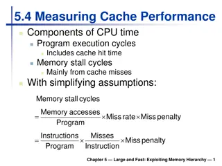
Examples: (2-way assoc, 64B line size, 1 array, 32 nm) Access Time vs Cache Size Access Time 0.6 0.5 0.4 Access Time (ns) 0.3 0.2 0.1 0 0 20000 40000 60000 80000 100000 120000 140000 Cache Size (bytes)
Area vs Cache Size Area 0.6 0.5 0.4 Area (mm2) 0.3 0.2 0.1 0 0 20000 40000 60000 80000 100000 120000 140000 Cache Size (bytes)
Cache Size vs Power Power 0.3 0.25 Power (W), Max. Frequency 0.2 0.15 0.1 0.05 0 0 20000 40000 60000 80000 100000 120000 140000 Cache Size (bytes)
Outline Modeling and simulating caches Structure of a large L2 cache Non-uniform Caches S-NUCA D-NUCA R-NUCA
Structure of a Modern Processor Typical L2 caches in a chip are fairly large: order of MBs It is thus necessary to divide them into many banks We thus have an array of banks A lot of modern chips have many cores (OOO pipelines) also (more later) There are many ways to organize cores and cache banks Rim Layout Checkerboard Layout Core Cache bank
How do you pass messages in such a system? Need an on-chip network Also called Network-on-chip (NoC) First create groups of co-located cores and cache banks Called a tile Associate a network element (router) with each tile. Elements in each tile are connected to each other using regular electrical links. All of them are also connected to the router (one per each tile). Communication Element Router
Passing Messages - II Connect all the routers with an on-chip network Routers are connected by electrical links (or hops) Destination Sending a message Source
A Network Router Local Tile Router Router Router Router Router
Network Delays Two routers are connected with a set of wires We cannot have many wires in parallel We typically cannot have more than 64-128 wires in parallel Means, we cannot send more than 64-128 bits at a time 64-128 bits 8-16 bytes Each such packet is also called a flit in an NoC If we are reading a 64 byte cache line We need to break it into 4-8 flits Send one flit after the other A lot of networks typically a head flit and a tail flit also Head flit Body flit Body flit Tail flit
Network Delays Flits typically 1 cycle to traverse a hop Sending delay by the transmitter Signal propagation time Receiving delay What does the router do? If the flit belongs to the local time send it to the local tile Figure out the next router to send the packet to Take congestion and deadlocks into account Router has a delay of 2-3 cycles Total delay: at least 3-4 cycles
Network Delays How long will it take to go from one end to the other in this network? 6 hops, assume 4 cycles per hop 24 cycles
Non Uniform Caches L2/L3 caches are large. If you find data in a nearby bank a couple of cycles If it is a remote bank 20-50 cycles (depending on the size of the network and the degree of congestion) Cache access times can be very variable depending on where the data is This is called a non-uniform cache (NUCA cache) Can we take advantage of this non-uniformity? ANSWER: Place frequently used data closer
Outline Modeling and simulating caches Structure of a large L2 cache Non-uniform Caches S-NUCA D-NUCA R-NUCA
S-NUCA (static NUCA) Simplest scheme: Map cache lines to cache banks Give a cache line we know which cache bank it maps to How to do the mapping Solution 1: Byte within a block Tag Bank id Set id Solution 2: Byte within a block Set id Bank id Tag Tradeoffs: Bank locality vs homogenizing bank accesses
D-NUCA (Dynamic NUCA) Let us now look at a method of bringing frequently used data closer Bank set sets of banks Bank set 1 Bank set 8
Operation of the Protocol Given an address Map it to a bank set Byte within a block Tag Bank set id Set id Search the bank set If you find the line, declare a cache hit Otherwise declare a miss and fetch it from the lower level Three search strategies Sequential Two-way Broadcast
Search Strategies: Start from the home bank (closest to the core in the bank set) Sequential Search start from home bank Two-way Search Broadcast Search
After a Hit/Miss Decision Hit decision Send the block to the requesting core Promote the block Move it closer to the home bank (Migration) Bring it to a nearer bank (closer to the home bank) If there is an empty block in the set in the new bank no problem Otherwise swap the blocks Bringing blocks closer to the home bank (consistent with temporal locality) Miss decision Fetch the block from the lower level Either insert it into the nearest bank or the farthest bank (depends on the strategy)
Eviction and Migration Assume that a block needs to be evicted Solution 1: Move it to the lower level Solution 2: Move it away from the home bank. Need to tag each line with the id of the requesting core Advantages Keeps data close to requesting cores Brings data closer depending upon usage Gives a block multiple chances Upon an eviction move it to block slightly further away Search policy, location, migration and eviction are important design decisions
R-NUCA Break down accesses into three types Instructions (read only) Data-private Data-shared Since instructions are read-only, thus they can be replicated Data cannot be replicated (very complex) Use OS mechanisms to map pages as: instruction, data-private, and data-shared Save this information in the TLBs
Instructions Overlapping clusters Create small clusters of 4 tiles Can be overlapping or non-overlapping If they are overlapping A tile can be a part of multiple clusters Search protocol Consider the 2 bits in the block address above the set index bits 2 bits 4 combinations For each combination store the id of the tile that we need to search Note that a tile can be a part of multiple clusters Ensure that for all the tiles in the cluster that we search all the blocks with the same value of the 2 bits map to the same cluster If there is a miss in the cluster search in a designated remote bank (SNUCA)
Mapping Clusters in R-NUCA Rotational Interleaving 11 00 01 10 01 10 11 00 Cluster 11 00 01 10 Randomly assign a RID of 00 to a tile 01 10 11 00 RIDs are contiguous along each row Differ by n/2 (for n = 4) across a column Let A = (a1, a2) be 2 bits in the block address to the left (more significant) of the set index Compute ( RID - A ) Result: 0 (current), -1 (right), 1 (left), 2 or -2 (down) Access the bank. This is where the instruction line should be kept.
Data Private data Store it only within the bank in the tile Shared data Use SNUCA Advantages: Limited replication ensures good instruction hit rates Does not add the complexity of maintaining replicas for read-write data


")
")