Derivation of State Graphs and Tables for Sequential Circuit Design
Explore the process of deriving state graphs and tables for Mealy and Moore sequential circuit designs in Chapter 14. Learn to create state graphs, transition tables, output functions, and finalize circuits for efficient sequence detection. Gain insights into the significance of each state and input sequences required for circuit functionality.

Download Presentation

Please find below an Image/Link to download the presentation.
The content on the website is provided AS IS for your information and personal use only. It may not be sold, licensed, or shared on other websites without obtaining consent from the author. If you encounter any issues during the download, it is possible that the publisher has removed the file from their server.
You are allowed to download the files provided on this website for personal or commercial use, subject to the condition that they are used lawfully. All files are the property of their respective owners.
The content on the website is provided AS IS for your information and personal use only. It may not be sold, licensed, or shared on other websites without obtaining consent from the author.
E N D
Presentation Transcript
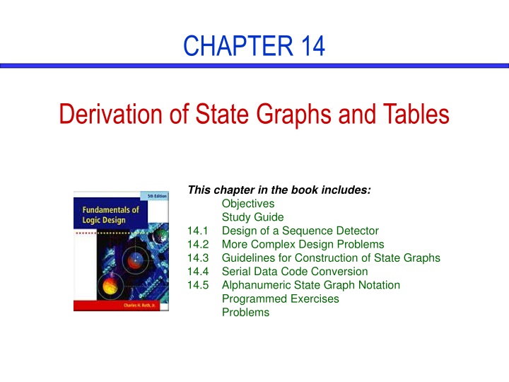
CHAPTER 14 Derivation of State Graphs and Tables This chapter in the book includes: Objectives Study Guide 14.1 Design of a Sequence Detector 14.2 More Complex Design Problems 14.3 Guidelines for Construction of State Graphs 14.4 Serial Data Code Conversion 14.5 Alphanumeric State Graph Notation Programmed Exercises Problems
Objectives 1. Given a problem statement for the design of a Mealy or Moore sequential circuit, find the corresponding state graph and table. 2. Explain the significance of each state in your graph or table in terms of the input sequences required to reach that state. 3. Check your state graph using appropriate input sequences.
14.1 Design of a Sequence Detector Sequence Detector to be Designed Z=1 for input sequence of 101 X = 0 0 1 1 0 1 1 0 0 1 0 1 0 1 0 0 Z = 0 0 0 0 0 1 0 0 0 0 0 1 0 1 0 0 (time: 0 1 2 3 4 5 6 7 8 9 10 11 12 13 14 15)
14.1 Design of a Sequence Detector Mealy Formation of State Graph
14.1 Design of a Sequence Detector Mealy State Graph for Sequence Detector
14.1 Design of a Sequence Detector State Table Present Output Present state Next State X = 0 X = 1 X = 0 X =1 S0 S1 S2 S0 S2 S0 S1 S1 S1 0 0 0 0 0 1 Transition Table with State Assignment A+ B+ Z AB X = 0 X = 1 X = 0 X =1 00 01 10 00 10 00 01 01 01 0 0 0 0 0 1
14.1 Design of a Sequence Detector Map for the Output Function Z (from Table 1,2)
14.1 Design of a Sequence Detector Final Circuit
14.1 Design of a Sequence Detector Moore Machine Design Process
14.1 Design of a Sequence Detector Moore State Graph for Sequence Detector
14.1 Design of a Sequence Detector Transition Table with State Assignment State Table Present State Next State X = 0 S0 S2 S0 S2 Present Output (Z) A+B+ X = 1 AB Z X = 0 00 11 00 11 X = 1 01 01 10 01 00 01 11 10 0 0 0 1 S0 S1 S2 S3 S1 S1 S3 S1 0 0 0 1
14.2 More Complex Design Problems The circuit to be designed (Mealy) Output Z=1 if input sequence ends in either 010 or 1001 X= 0 0 1 0 1 0 0 1 0 0 0 1 0 0 1 1 0 a b c d e f Z= 0 0 0 1 0 1 0 1 1 0 0 0 1 0 1 0 0
14.2 More Complex Design Problems Formation of State Graph (010 sequence) state S0 S1 S2 S3 sequence received reset 0 01 010
14.2 More Complex Design Problems Formation of State Graph (1001 sequence) state S0 S1 S2 S3 S4 S5 sequence ends in reset 0 (but not 10) 01 10 1 (but not 01) 100
14.2 More Complex Design Problems Completed State Graph for a Sequence Detector to be Designed state S0 S1 S2 S3 S4 S5 sequence ends in reset 0 (but not 10) 01 10 1 (but not 01) 100
14.2 More Complex Design Problems The circuit to be designed (Moore) Output Z=1 if the total number of 1 s received is odd and at least two consecutive 0 s have been received X= 1 0 1 1 0 0 1 1 a b c d e Z= (0) 0 0 0 0 1 0 1
14.2 More Complex Design Problems Formation of State Graph (Step 1)
14.2 More Complex Design Problems Formation of State Graph (Step 2) state S0 S1 S2 S3 S4 sequence ends in reset or even 1 s odd 1 s even 1 s and ends in 0 even 1 s and 00 has occurred 00 has occurred and odd 1 s
14.2 More Complex Design Problems Completed State Graph for a Sequence Detector to be Designed state S0 S1 S2 S3 S4 S5 sequence ends in reset or even 1 s odd 1 s even 1 s and ends in 0 even 1 s and 00 has occurred odd 1 s and 00 has occurred odd 1 s and ends in 0
14.3 Guidelines for Construction of State Graphs 1. Construct some sample input and output sequences to make sure that you understand the problem statement. 2. Determine under what conditions the circuit should reset to its initial state. 3. If only one or two sequences lead to a non-zero output, a good way to start is to Construct a partial state graph for those sequences. 4. Determine what sequences or groups of sequences must be remembered by the circuit and set up states accordingly. 5. Each time you add an arrow to the state graph, determine it can go to one of the previously defined states or whether a new state must be added 6. Check your state graph to make sure there is one and only one path leaving each state for each combination of values of the input variables 7. When your state graph is complete, test it by applying the input sequences formulated in part1 and making sure the output sequences are correct
14.3 Guidelines for Construction of State Graphs Example 1: Z=1 when input sequence 0101 or 1001 occurs. The circuit resets after every four inputs. Mealy Circuit A typical sequence of input and output X = Z = 0101 0001 0010 0000 1001 0001 0100 0000
14.3 Guidelines for Construction of State Graphs Partial State Graph for Example 1 State Sequence Received S0 S1 S2 S3 S4 reset 0 1 01 or 10 010 or 100 The circuit goes to the same state if either 01 or 10 received.
14.3 Guidelines for Construction of State Graphs Complete State Graph for Example 1 state S0 S1 S2 S3 S4 S5 sequence received Reset 0 1 01 or 10 010 or 100 two inputs received, no 1 output is possible three inputs received, no 1 output is possible S6
14.3 Guidelines for Construction of State Graphs Example 2: Z1=1 every time the input sequence 100 is completed, provided that the sequence 010 has never occurred. Z2=1 every time the input sequence 010 is completed Once Z2=1 occurred, Z1=1 can never occur but not vice versa Find Mealy circuit. A typical sequence of input and output X = 1 0 0 1 1 0 0 1 0 1 0 1 0 0 1 0 1 1 0 1 0 0 Z1= 0 Z2= 0 0 0 1 0 0 0 0 0 0 0 1 0 0 0 0 1 0 0 0 1 0 0 0 1 0 0 0 0 0 1 0 0 0 0 0 0 0 0 0 1 0 0
14.3 Guidelines for Construction of State Graphs Partial Graphs for Example 2
14.3 Guidelines for Construction of State Graphs State Descriptions for Example 2 stats S0 S1 S2 S3 S4 S5 S6 S7 Description No progress on 100 Progress of 1 on 100 Progress of 10 on 100 No progress on 100 Progress of 10 on 100 No progress on 010 No progress on 010 Progress of 0 on 010 Progress of 0 on 010 Progress of 01 on 010 Progress of 0 on 010 Progress of 01 on 010 No progress on 010 010 has never occurred 010 has occurred
14.3 Guidelines for Construction of State Graphs State Graphs for Example 2
14.3 Guidelines for Construction of State Graphs State Table for Example 2 Present state S0 S1 S2 S3 S4 S5 S6 S7 Next X = 0 S3 S2 S3 S3 S5 S5 S5 S5 State X = 1 S1 S1 S4 S4 S1 S6 S7 S7 Output X = 0 00 00 10 00 01 00 01 00 (Z1 Z2) X = 1 00 00 00 00 00 00 00 00
14.3 Guidelines for Construction of State Graphs Example 3: Two inputs X1, X2, One output Z (a) The input sequence X1X2=01, 11 causes the output 0 (b) The input sequence X1X2=10, 11 causes the output 1 (c) The input sequence X1X2=10, 01 causes the output to change Derive a Moore state graph. Previous Input (X1X2) 00 or 11 00 or 11 01 01 10 10 Output (Z) State Designation 0 1 0 1 0 1 S0 S1 S2 S3 S4 S5
14.3 Guidelines for Construction of State Graphs State Table for Example 3 Present State S0 S1 S2 S3 S4 S5 Next state 01 S2 S3 S2 S3 S3 S2 Z X1X2 = 00 S0 S1 S0 S1 S0 S1 11 S0 S1 S0 S0 S1 S1 10 S4 S5 S4 S5 S4 S5 0 1 0 1 0 1
14.3 Guidelines for Construction of State Graphs State Graph for Example 3
14.4 Serial Data Code Conversion Serial Data Transmission
14.4 Serial Data Code Conversion Coding Schemes for Serial Data Transmission
14.4 Serial Data Code Conversion Non-Return-to-Zero Inverted (NRZI) The two level NRZI signal has a transition at a clock boundary if the bit being transmitted is a logical 1, and does not have a transition if the bit being transmitted is a logical 0.
14.4 Serial Data Code Conversion Manchester code Each bit is transmitted in a fixed time (the "period"). A 0 is expressed by a low-to-high transition, a 1 by high-to-low transition. The transitions which signify 0 or 1 occur at the midpoint of a period. Transitions at the start of a period are overhead and don't signify data.
14.4 Serial Data Code Conversion Mealy circuit for NRZ to Manchester Conversion
14.4 Serial Data Code Conversion Sequence Detector to be Designed (Mealy) Present State S0 S1 S2 Next State X = 0 S1 S0 - Output (Z) X = 0 0 1 - X = 1 S2 - S0 X = 1 1 - 0 (d) State table
14.4 Serial Data Code Conversion Moore Circuit for NRZ-to-Manchester Conversion
14.4 Serial Data Code Conversion Moore Circuit for NRZ-to-Manchester Conversion Prese nt State S0 S1 S2 S3 Next State Present X = 0 S1 S2 S1 - X = 1 S3 - S3 S0 Output (Z) 0 0 1 1 (c) State table
14.5 Alphanumeric State Graph Notation State Graphs with Variable Names on Arc Labels
14.5 Alphanumeric State Graph Notation State Table for Fig 14-22 PS NS Output FR = 00 S0 S0 S0 01 S0 S0 S0 10 S0 S0 S0 11 S0 S0 S0 Z1 1 0 0 Z2 0 1 0 Z3 0 0 1 S0 S0 S0 + + = + = The result : ' ' ' ' 1 F F R F R F F If we AND together every possible pair of arc labels emanating from S0, we get , 0 = , 0 = = ' ' ' ' ' ' , 0 F F R F F R F R F R


