Design Considerations in Powder Metallurgy
Use of PM techniques is suited to certain types of production situations and part designs. The Metal Powder Industries Federation classifies PM part designs into four categories based on pressing difficulty. This system guides the geometries suitable for conventional PM pressing methods. PM processing economics often require large part quantities. PM can fabricate parts with controlled porosity, even in unusual metals. Design features like undercuts and holes must be considered for successful PM fabrication. Screw threads require post-sinter machining, while chamfers and corner radii are achievable through PM pressing.
Download Presentation

Please find below an Image/Link to download the presentation.
The content on the website is provided AS IS for your information and personal use only. It may not be sold, licensed, or shared on other websites without obtaining consent from the author.If you encounter any issues during the download, it is possible that the publisher has removed the file from their server.
You are allowed to download the files provided on this website for personal or commercial use, subject to the condition that they are used lawfully. All files are the property of their respective owners.
The content on the website is provided AS IS for your information and personal use only. It may not be sold, licensed, or shared on other websites without obtaining consent from the author.
E N D
Presentation Transcript
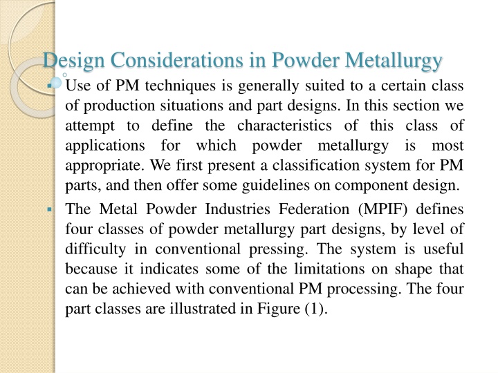
Design Considerations in Powder Metallurgy Use of PM techniques is generally suited to a certain class of production situations and part designs. In this section we attempt to define the characteristics of this class of applications for which powder appropriate. We first present a classification system for PM parts, and then offer some guidelines on component design. The Metal Powder Industries Federation (MPIF) defines four classes of powder metallurgy part designs, by level of difficulty in conventional pressing. The system is useful because it indicates some of the limitations on shape that can be achieved with conventional PM processing. The four part classes are illustrated in Figure (1). metallurgy is most
Figure (1): Four classes of PM partsside view shown; cross section is circular: (a) Class I simple thin shapes that can be pressed from one direction; (b) Class II simple but thicker shapes that require pressing from two directions; (c) Class III two levels of thickness, pressed from two directions; and (d) Class IV multiple levels of thickness, pressed from two directions, with separate controls for each level to achieve proper densification throughout the compact.
The MPIF classification system provides some guidance concerning part geometries that are suited to conventional PM pressing techniques. Economics of PM processing usually require large part quantities to justify the cost of equipment and special tooling required. Minimum quantities of 10,000 units are suggested, although exceptions exist. Powder metallurgy is unique in its capability to fabricate parts with a controlled level of porosity. Porosities up to 50% are possible. PM can be used to make parts out of unusual metals and alloys materials that would be difficult if not impossible to fabricate by other means. The geometry of the part must permit ejection from the die after pressing; this generally means that the part must have vertical or near-vertical sides, although steps in the part are permissible as suggested by the MPIF classification system (Figure 1). Design features such as undercuts and holes on the part sides, as shown in Figure 2, must be avoided. Vertical undercuts and holes, as in Figure 3, are permissible because they do not interfere with ejection. Vertical holes can be of cross sectional shapes other than round (e.g., squares, keyways) without significant increases in tooling or processing difficulty.
Screw threads cannot be fabricated by PM pressing; if required, they must be machined into the PM component after sintering. Chamfers and corner radii are possible by PM pressing, as shown in Figure 4. Problems are encountered in punch rigidity when angles are too acute. Wall thickness should be a minimum of 1.5mm(0.060 in) between holes or a hole and the outside part wall, as indicated in Figure 5. Minimum recommended hole diameter is 1.5 mm (0.060 in).
Figure (2) Part features to be avoided in PM: (a) side holes and (b) side undercuts. Part ejection is impossible.
Figure (3): Permissible part features in PM: (a) vertical hole, blind and through, (b) vertical stepped hole, and (c) undercut in vertical direction. These features allow part ejection.
Figure (4): Chamfers and corner radii are accomplished but certain rules should be observed: (a) avoid acute chamfer angles; (b) larger angles are preferred for punch rigidity; (c) small inside radius is desirable; (d) full outside corner radius is difficult because punch is fragile at corner s edge; (e) outside corner problem can be solved by combining radius and chamfer.
Figure (5): Minimum recommended wall thickness (a) between holes or (b) between a hole and an outside wall should be 1.5 mm (0.060 in).
