Differences in Control Modes for Power Converter Design
Explore the reasons behind variations in equations, dead times, and current peaks between DC and non-DC control modes in power converter designs. Gain insights into energy perspectives and waveform behaviors.

Download Presentation

Please find below an Image/Link to download the presentation.
The content on the website is provided AS IS for your information and personal use only. It may not be sold, licensed, or shared on other websites without obtaining consent from the author. If you encounter any issues during the download, it is possible that the publisher has removed the file from their server.
You are allowed to download the files provided on this website for personal or commercial use, subject to the condition that they are used lawfully. All files are the property of their respective owners.
The content on the website is provided AS IS for your information and personal use only. It may not be sold, licensed, or shared on other websites without obtaining consent from the author.
E N D
Presentation Transcript
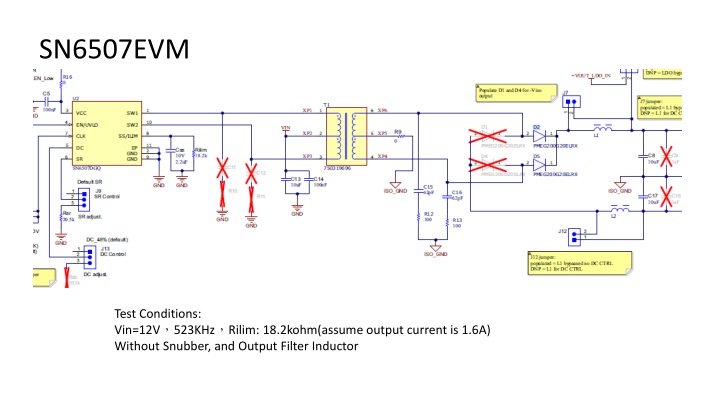
SN6507EVM Test Conditions: Vin=12V 523KHz Rilim: 18.2kohm(assume output current is 1.6A) Without Snubber, and Output Filter Inductor
Probe Setting CH2:SW2_V CH1:SW2_I CH3:SW1_V CH4:SW1_I Vin = 12V Vo = 18.1V No-Load (RDC=51k Duty Control) Vin = 12V Vo = 22.8V No-Load (No RDC) Deadtime is different? Vin = 12V/0.29A Vo = 14.57V Load = 0.2A (RDC=51k Duty Control) Vin = 12V Vo = 15.7V Load = 0.2A No RDC Peak=448mA Peak=900mA 200mA 500mA Peak current is different?
Vin=12V523KHzRilim=18.2kohm(1.6A)Electronics Load = 0.2A Without Snubber and inductor filter CH2:SW2_V CH1:SW2_I CH3:SW1_V CH4:SW1_I Vin = 12V Vo = 15.8V Load = Short circuit
Questions: 1. Why is there a different on equation between DC and non-DC control mode? 2. On the page 2 waveform, we found the deadtime is difference between DC and non-DC mode. How come? And also, the current is 2 times difference in between? Could you help to explain from energy s point of view? 3. On the page 3 waveform, when output rail is shorted to ground, there re always 4 PWM cycles shutting off and then turn on With 4 PWM cycles. In the d/s, it says when short event is happened, PWM will be cycle-by-cycle protection. Is this waveform behavior correct?
Answers: 1. Why is there a different on equation between DC and non-DC control mode? For converter designs with wide-input range but no duty cycle control, the turns ratio needs to take the minimum input voltage into consideration. When Duty Cycle control is enabled, the requirement of turns-ratio doubles as duty cycle is halved from 48% to 25%.
2. On the page 2 waveform, we found the deadtime is difference between DC and non-DC mode. How come? And also, the current is 2 times difference in between? Could you help to explain from energy s point of view? The peak current is due to primary inductance of the transformer and the change in on-time duration. Is this deadtime difference observed with same transformer?
3. On the page 3 waveform, when output rail is shorted to ground, therere always 4 PWM cycles shutting off and then turn on With 4 PWM cycles. In the d/s, it says when short event is happened, PWM will be cycle-by-cycle protection. Is this waveform behavior correct? This depends on type of short, hard short or soft short. In soft-short the converter goes into hiccup mode on hitting the programmed OCP threshold, the driver will be shut-off for 100 ns (typical), and then retry driving. If the OCP trips again, the cycle continues.


,Electronics Load =")