Different Structure Rubber with Air Analysis
Explore the interaction between rubber structures and air in a 2D ALE simulation, including Lagrangian and Eulerian approaches, geometry and mass considerations, contact between structures, symmetry plane motion, boundary conditions, and more. Discover the complexities of modeling compressible materials and the motion of different parts within the system.

Download Presentation

Please find below an Image/Link to download the presentation.
The content on the website is provided AS IS for your information and personal use only. It may not be sold, licensed, or shared on other websites without obtaining consent from the author. If you encounter any issues during the download, it is possible that the publisher has removed the file from their server.
You are allowed to download the files provided on this website for personal or commercial use, subject to the condition that they are used lawfully. All files are the property of their respective owners.
The content on the website is provided AS IS for your information and personal use only. It may not be sold, licensed, or shared on other websites without obtaining consent from the author.
E N D
Presentation Transcript
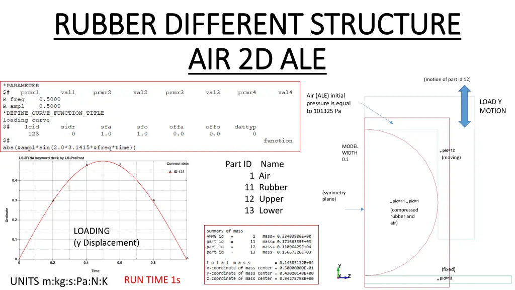
RUBBER DIFFERENT STRUCTURE RUBBER DIFFERENT STRUCTURE AIR 2D ALE AIR 2D ALE (motion of part id 12) Air (ALE) initial pressure is equal to 101325 Pa LOAD Y MOTION MODEL WIDTH 0.1 (moving) Part ID Name 1 Air 11 Rubber 12 Upper 13 Lower (symmetry plane) (compressed rubber and air) LOADING (y Displacement) (fixed) RUN TIME 1s UNITS m:kg:s:Pa:N:K
LAGRANGIAN Material attached to the mesh, mesh deforms due to a load ARBITARY LAGRANGIAN EULARIAN Two overlapping meshes, a background mesh (ALE) that can move but does not deform, and a material mesh (LAG) that deforms as it moves over the background mesh (ALE). Calculation is a TWO step process. LAGRANGIAN 1: Load applied to material mesh, it deforms ALE 2: The material has moved from one cell on the background mesh to another cell on the background mesh. Hence, need to remap, advect or redistribute the Lagrangian state element variables back onto the ALE background mesh.
GEOMETRY AND MASS Part ID Name 1 Air 11 Rubber 12 Upper 13 Lower
Symmetry Plane MOTION Symmetry Plane MOTION REACTION FORCE Y DIRECTION FIXED LOWER STRUCTURE REACTION FORCE Z DIRECTION MOVING UPPER STRUCTURE
BOUNDARY CONDITIONS
LOADING (y Displacement) CONSTANT PRESSURE LOAD 101325 Pa BOUNDARY PRESCRIBED MOTION
P = (gamma-1)*E/V or E = P*V/(gamma-1) (gamma-1)=0.4 for Air E = 1.01325e05*1.0/(0.4) = 253313 (PV = nRT Ideal Gas Law) PART ID S
RUN TIME NUMBER NODES ELEMENTS PARTS VERSION
Motion of upper structure Y DISPLACEMENT vs TIME Upper Structure (Moving) Rubber (Compressed) Lower Structure (fixed)
A B C VON MISES STRESS vs TIME D
Air Structure Upper Rubber Symmetry Plane PRESSURE IN AIR CORNER POCKETS Structure Lower
NB Just after t = 0.3s due to the large size of the ALE elements, the air is unable to flow out from the bottom right hand corner. Hence, a pressure build up occurs. ALE elements need to be smaller such that at t = 0.5s the pressure in that corner remains at 101325 Pa. Time = 0.3s EID A:1715 B:1755 C:1795 D:1835 E:2130 F:2131 Opening must be much greater than ALE element size for air to escape. Okay t<0.3s, not okay when t>0.3s A B C D E F (Opening)


*E/V or E = P*V/(gamma-1)")