Digital Communication: Basics and Components
Discover the fundamentals of digital communication, including analog to digital conversion, source coding, channel encoding, and modulation techniques. Learn about the process of transferring data reliably between sources and destinations through communication systems. Explore the block diagram of a typical communication system and delve into the roles of information sources, transmitters, channels, receivers, and information sinks. Gain insights into the importance of channels, physical mediums, noise, and the conversion of data forms. Explore the digital communication system through a comprehensive block diagram, highlighting key components such as A/D converters, modulators, encoders, decoders, and more.

Uploaded on | 2 Views
Download Presentation

Please find below an Image/Link to download the presentation.
The content on the website is provided AS IS for your information and personal use only. It may not be sold, licensed, or shared on other websites without obtaining consent from the author. If you encounter any issues during the download, it is possible that the publisher has removed the file from their server.
You are allowed to download the files provided on this website for personal or commercial use, subject to the condition that they are used lawfully. All files are the property of their respective owners.
The content on the website is provided AS IS for your information and personal use only. It may not be sold, licensed, or shared on other websites without obtaining consent from the author.
E N D
Presentation Transcript
DIGITAL Communication
Outline What is communication? Analog to Digital Conversion (A/D) Source Coding Channel Encoding Modulation Techniques
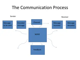
What is Communication? Communication is transferring data reliably point to another. from one Data could be: voice, video, images etc Communication system A system that allows transfer of information reliably between transmitter and receiver.
Block Diagram of a typical communicationsystem Transmitter Information Source Channel Receiver Destination
Information Source The source of data Data could be: human voice, video etc.. Data types: Discrete/Digital: Finite set of values Continuous/Analog : Infinite set of values Transmitter Converts the source data into a suitable form for transmission through signal processing Data form depends on the channel
Channel: The physical medium used to send the signal where the signal propagates till arriving to the destination. Physical Media (Channels): Wired : twisted pairs, coaxial cable, fiberoptics Wireless: Air,vacuum and water Every physical channel operates on a certain limited range of frequencies , that is called the channel bandwidth. Physical channels have another important drawback which is the Noise.
Receiver Reproducing the message in the received signal Example Speech signal at transmitter is converted into electromagnetic waves to travel over the channel. Once the electromagnetic waves are received properly, the receiver converts it back to a speech form. Information Sink The final stage/User
Digital Communication System Block Diagram Information Source A / D Converter Modulator Channel Encoder Source Encoder Channel Information Sink D /A Demodulator Channel Decoder Source Decoder Converter
Information source Analog Data: Microphone, speech signal, image, video etc. Digital Data: keyboard, binary numbers etc. Analog to Digital Converter (ADC) Sampling: Converting continuous time signal to a discrete timesignal Quantization: Converting the amplitude of the analog signal toa digital value Coding: Assigning a binary code to each finite amplitude in the signal
Source encoder Data Compression- carried out to convert the analog signal to digital form. Data Compaction carried out to produce a new data code that represents digital data more efficiently. Data Encryption Licensed user with the required key can only decode and receive the data.
Channel encoder: Controls the noise, detects and corrects the occur in the transmitted data due to noise in the channel. Modulator: Converts the digital data into analog signals at can be easily sent on the analog signals. Demodulator: Removes the carrier signal and reverse the process of the Modulator errors that can
Channel decoder: Detects and corrects the errors in the signal received from the channel Source decoder: Decompression & Decryption of the data into its original form. Digital to Analog Converter: Reverses the operation of the Analog to Digital Converter Needs techniques and knowledge about sampling, quantization, and coding methods. Information Destination
Advantages of Digital communication Ease of regeneration Pulses 0 , 1 Easy to use repeaters Noise immunity Better noise handling when using repeaters Digital circuits are less prone to interference and distortion Ease of Transmission Low error rates Reliability Ease of measurement
Advantages of Digital communication Ease of multiplexing Transmitting several signals simultaneously Use of modern technology Integrated Circuit Ease of encryption Security and privacy guarantee Handles most of the encryption techniques
Disadvantages The major disadvantage of digital transmission that it requires a greater transmission bandwidth or channel bandwidth to information in digital format as compared to analog format. Another disadvantage is the requirements of precise synchronization between the transmitter and the receiver. is communicate the same
Analog Signal to a Discrete Signal (A/D) Conversion Can be done through three basic steps: 1 Sampling 2 Quantization 3 Coding
Sampling Process of converting the continuous time signal to a discrete time signal. Sampling is done by taking Samples at specific regular time intervals. V(t) is an analog signal V(nTs) is the sampled signal Ts = positive real number that represent the spacing of the samplingtime n = sample number integer
Sampling Original Analog Signal BeforeSampling Sampled Analog Signal After Sampling
Sampling The closer the Ts value, the closer the sampled signal resemble the original signal. Sampling rate must be large enough to allow analog signals to be reconstructed accurately. We lose some values of the parts between each successive samples. original signal, the
Sampling Theorem A bandlimited signal having no spectral components above fmax (Hz), can be determined uniquely by values sampled at uniform intervals of Tsseconds, where An analog signal can be reconstructed from a sampled signal without any loss of information if and only if it is: Band limited signal The sampling frequency is at least twice the signal bandwidth
Quantization Quantization is the process of constraining an input from a continuous or large set of values (such as the real numbers) to a discrete set (such as the integers). Dynamic range of a signal The difference between the highest signal can takes. to lowest value the
Quantization In the Quantization process, the dynamic range of a signal is divided into L number of amplitude levels denoted by mk, where k = 1, 2, 3, .. L L is an integer power of 2 L =2k K is the number of bits needed to represent the amplitude level. For example: If we divide the dynamic range into 8 levels, L = 8 = 23 Weneed 3 bits to represent each level.
Quantization Example: Suppose we have an analog signal with the values between 0 and 10. If we divide the signal into four levels. We have m1 m2 m3 m4 [ 0, 2.5] [ 2.5, 5] [ 5 ,7.5] [ 7.5,10]
Quantization Original Analog Signal Quantized Analog Signal
Quantization Original Discrete Signal Quantized Discrete Signal
Quantization The more quantization levels taken, the error between the original and quantized signal. Quantization step smaller the The smaller the , the smaller the error.
Coding Assigning a binary code to each quantization level. For example, if we have quantized a signal into levels, the coding process is done as the following: 16 Step Code Step Code Step Code Step Code 0 0000 4 0100 8 1000 12 1100 1 0001 5 0101 9 1001 13 1101 2 0010 6 0110 10 1010 14 1110 3 0011 7 0111 11 1011 15 1111
Coding The binary codes are represented as pulses Pulse means 1 No pulse means 0 After coding process, the signal is ready to be transmitted through the channel. And therefore, completing the A/D conversion of an analog signal.
Transmission After encoding the binary data, the data is now ready to be transmitted through the physical channel In order to transmit the data in the physical channel we must convert the data back to an electrical signal Convert it back to an analog form This process is called modulation
Modulation Modulation is the process of changing a parameter of a signal using another signal. The most commonly used signal type is the sinusoidal signal that has the form of : V(t) = A sin ( wt + ) A : amplitude of the signal w : radian frequency : Phase shift
Modulation If the carrier signal amplitude changes with the message signal, then the process is called as amplitudemodulation. in accordance If the carrier signal frequency changes in accordance with the message signal, then this process is known as frequency modulation.
Digital Data Transmission There Transmission: are two types of Digital Data 1) Base-Band data transmission Uses low frequency carrier signal to transmit the data 2) Band-Pass data transmission Uses high frequency carrier signal to transmit the data
Transmission Transmission bandwidth: the transmission bandwidth of a communication system is the band of frequencies allowed for signal transmission, in another word it is the band of frequencies at which we are allowed to transmit the data. Bit Rate: It is the number of bits transferred between devices per second. If each bit is represented by a pulse of width Tb then the bit rate is
Example Bit ratecalculation Suppose that we have a binary data source that generates bits. Each bit is represented by a pulse of width Tb = 0.1 ms. Calculate the bit rate for the source. Solution: 1 1 10000 bits/sec Rb 10 3 0.1 T b
Baud rate (Symbol rate) The numberof symbolstransmittedper second through the communication channel. The symbolrate is relatedto the bit rate by the following equation: Rb = bit rate Rs = symbol rate N= Number of bits per symbol
Baud rate (Symbol rate) We usually use symbols to transmit data when the transmission bandwidth is limited For example, we need to transmit a data at high rate and the bit duration Tb is very small; to overcome this problem we take a group of more than one bit, say 2. By transmitting symbols rather than bits we can reduce the spectrum of the transmitted signal.
Example A binary data source transmits binary data, the bit duration is 1 sec, Suppose we want to transmit symbols rather than bits, if each symbol is represented by four bits. what is the symbol rate? Each bit is represented by a pulse of duration 1 s, hence the bit rate 1 1000000 bits/sec Rb 1 106
Therefore, the symbol rate will be 1000000 4 Rb 250000 symbols/sec Rs N
Bandpass Data Transmission In communication, we use modulation for several particular: To transmit the message signal through the communication channel efficiently. To transmit several signals at the same time over a communication link through the process of multiplexing or multiple access. To simplify the design of the electronic systems used to transmit the message. by using modulation we can easily transmit data with low loss. reasons in
Bandpass Digital Transmission Digital modulation is the process by which digital symbols are transformed into wave-forms that are compatible with the characteristics of the channel. The following are the general steps used by the modulator to transmit data 1. Accept incoming digital data 2. Group the data into symbols 3. Use these symbols to set or change the phase, frequency or amplitude of the reference carrier signal appropriately.
Bandpass Modulation Techniques Amplitude Shift Keying (ASK) Phase Shift Keying (PSK) Frequency Shift Keying (FSK) Multilevel Signaling (MaryModulation) Mary Amplitude Modulation Mary Phase Shift Keying (MaryPSK) Mary Frequency Shift Keying (MaryFSK) Quadrature Amplitude Modulation (QAM)
Amplitude Shift Keying (ASK) In ASK the binary data modulates the amplitude of the carrier signal.
Phase Shift Keying(PSK) In PSK the binary data modulates the phase of the carrier signal.
Frequency Shift Keying(FSK) In FSK the binary data modulates the frequency of the carriersignal.


")


")
")


")
")
")
")