Digital Logic Design

In this lecture, we delve into the fundamentals of sequential networks, focusing on flip-flops, bistable elements, and timing considerations. Understanding how synchronous and asynchronous networks operate is crucial in digital logic design. Discover the essential concepts and applications of flip-flops in memory storage and feedback circuits to enhance your knowledge in digital logic design.

Download Presentation

Please find below an Image/Link to download the presentation.
The content on the website is provided AS IS for your information and personal use only. It may not be sold, licensed, or shared on other websites without obtaining consent from the author.If you encounter any issues during the download, it is possible that the publisher has removed the file from their server.
You are allowed to download the files provided on this website for personal or commercial use, subject to the condition that they are used lawfully. All files are the property of their respective owners.
The content on the website is provided AS IS for your information and personal use only. It may not be sold, licensed, or shared on other websites without obtaining consent from the author.
E N D
Presentation Transcript
Digital Logic Design Lecture 22
Announcements Homework 7 due today Homework 8 on course webpage, due 11/20. Recitation quiz on Monday on material from Lectures 21,22
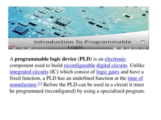
Agenda Last time: Programmable Logic Devices (5.7-5.10) This time: New topic: Flip-flops The Basic Bistable Element (6.1) Latches (6.2) Timing Considerations (6.3) Master-Slave Flip-Flops (6.4) Edge-Triggered Flip-Flops (6.5)
Sequential Networks The logic networks studied so far are combinational networks: The outputs at any instant depend only upon the inputs present at that instant. Sequential Network: The outputs at any instant are dependent not only upon the inputs present at that instant but also upon the past history of inputs. Sequential networks have memory. The information preserved is referred to as the internal state, secondary state, or state of the network.
Sequential Networks Synchronous sequential network Behavior is determined by the values of the signals at only discrete instants of time. Master-clock generator which produces a sequence of clock pulses that sample the input. Asynchronous sequential network Behavior of the network is immediately affected by the input signal changes.
Flip-Flop The basic logic element that provides memory in many sequential networks. Flip-flop itself is a simple sequential network. All sequential networks require the existence of feedback. Feedback is present in flip-flop circuits. Flip-flop has two stable conditions. Each of this is associated with a state or storage of a binary symbol.
The Basic Bistable Element Central to all flip-flop circuits. Has two outputs ?,? Two stable states: ? = 0;? = 1;? = 1;? = 1;? = 0;? = 0;? = 0; ? = ? = ? = 0;? = ? = ? = 1 ? = 1;? = 0;? = 0;? = 0;? = 1;? = 1;? = 1; ? = ? = ? = 1;? = ? = ? = 0
The Basic Bistable Element When output line ? = 1 the element is storing a 1; when output line ? = 0 the element is storing a 0. There is one more equilibrium condition that can exist. Occurs when the two output signals are halfway between logic-0 and logic-1. Known as metastable state. Any small change causes the element to enter one of its two stable states. Amount of time a device can stay in its metastable state is unpredictable. Metastable state must be avoided.
The Basic Bistable Element Has no inputs. When power is applied, it becomes stable in one of its two stable states and remains in this state until power is removed. To be useful, must be able to force the device into a particular state. A flip-flop is a bistable device, with inputs, that remains in a given state as long as power is applied and until input signals are applied to cause its output to change. Inputs to flip-flops: Asynchronous or direct input: a signal change produces an immediate change in the state of the flip-flop. Synchronous input: A signal change does not immediately affect the state of the flip-flop. Affects it only when some control signal (clock) occurs.
Latches Latches are one class of flip-flops The timing of the output changes is not controlled The output responds immediately to changes on the input lines. Input lines are continuously being interrogated. Sections 6.4,6.5: flip-flops in which the timing of the output changes is controlled.
The SR (set-reset) Latch Cross-coupling of two NOR gates. Two inputs: S, R referred to as the set and reset inputs Two outputs: ?,? S = R = 0 logic diagram simplifies to basic bistable element R = 1; S = 0 latch is reset If R is returned to 0 then latch retains its present state S = 1; R = 0 latch is set S,R are asynchronous inputs
The SR (set-reset) Latch Cross-coupling of two NOR gates. Two inputs: S, R referred to as the set and reset inputs Two outputs: ?,? Consider the case where S = R = 1 Output of both NOR gates becomes 0, not complementary When inputs return to 0: If one input returns to 0 before the other, the last input to stay at 1 determines the final state. If both inputs return to 0 simultaneously, the device may enter its metastable state. Final state is unpredictable. S = R = 1 regarded as forbidden state
Next state is the same as the previous state. The SR Latch + indicates the ?+,? response of the latch at the ?,? output terminals as a consequence of applying the various inputs. ?+is called the next state of the latch.
The ? ? Latch Cross-coupling of two nand-gates When ? = ? = 1 logic diagram reverts to the basic bistable element. Device has 2 stable states.
The Gated SR Latch Inputs for SR Latch and ? ? Latch are asynchronous. A change in the value of the inputs causes an immediate change of the outputs. Frequently desirable to prevent input activation signals from affecting the state of the latch immediately. gated SR latch or SR latch with enable is used.
The Gated SR Latch ? ? Latch along with 2 additional NAND gates and a control input C. C is referred to as enable, gate or clock input. C determines when the S and R inputs become effective. As long as C input is 0, outputs of NAND gates are 1, keeps the ? ? Latch in its current stable state. Any changes to S,R are blocked. Output is latched in its present state. When C is 1, the latch behaves as an SR Latch. If S = R = C = 1 then ? = ? = 1. If C then goes to 0, can enter metastable state.
The Gated D Latch The latches discussed thus far each has an input combination that is not recommended. The gated D (data) latch does not have this problem. Gated SR-latch in which a not-gate is connected between the S and R terminals. Why does this help?
Timing Considerations Responses to inputs are not really immediate, but occur after some appropriate time delay. To achieve desired responses, certain timing constraints must be satisfied.
Propagation Delays The propagation delay is the time it takes a change in an input signal to produce a change in an output signal. Propagation delay from low to high: ???? Propagation delay from high to low: ???? In general, these may be different.
Timing Diagram Propagation delays from high-low, low-high assumed equal. When S = R = 1, both ?,? become 0. ?15, signals on S, R are simultaneously changed from 1 to 0. Response of latch is unpredictable. Can be in 0-state, 1-state or metastable state. Application of 1 on the set input terminal returns the latch to predictable.
Minimum Pulse Width Another specification stated by the manufacturers of latches is that of a minimum pulse width ??(???). Minimum amount of time a signal must be applied in order to produce a desired result. Failure to satisfy the constraint may cause unintended change or have the latch enter its metastable state.
Setup and Hold Times Consider timing diagram for a gated D latch Q-output follows the input signal at D whenever the enable signal C = 1. When C = 0, changes are ignored. Consider times ?3,?6,?11,?14. C is returned to 0. Output latches onto its current state. To guarantee latching action: constraint is placed on D signal. Must not change right before and after C goes from 1 to 0. Setup time: minimum time ??? that D signal must be held fixed before the latching action. Hold time: minimum time ? that D signal must be held fixed after the latching action.
Unpredictable Response in a gated D latch


 Latch")
 Latch")