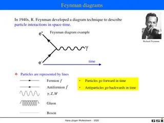
Digital System State Diagrams Overview
State diagrams in digital systems represent states using binary numbers and illustrate state transitions based on inputs. Circles depict states, lines show transitions with input values, and outputs are displayed relevantly. Moore machines present outputs inside states, while Mealy machines show outputs on transitions.

Download Presentation

Please find below an Image/Link to download the presentation.
The content on the website is provided AS IS for your information and personal use only. It may not be sold, licensed, or shared on other websites without obtaining consent from the author.If you encounter any issues during the download, it is possible that the publisher has removed the file from their server.
You are allowed to download the files provided on this website for personal or commercial use, subject to the condition that they are used lawfully. All files are the property of their respective owners.
The content on the website is provided AS IS for your information and personal use only. It may not be sold, licensed, or shared on other websites without obtaining consent from the author.
E N D
Presentation Transcript
ECE 352 Digital System Fundamentals State Diagrams State Diagrams 1 1 1
State Diagram A graphical depiction of the state table Circles represent the states in the diagram In an FSM circuit with N flip-flops, the state is encoded as an N-bit binary number N bits can represent up to 2Nstates Directed lines represent the state transitions Arrows indicate the direction of the transition Labeled with input value(s) that cause the transition Each line of the state table corresponds to a transition Circuit outputs shown where they are relevant Moore machine: inside the state circle Mealy machine: on the transitions State Diagrams 2 2 2
Example Moore Diagram Create state diagram based on state table Two states (Q=0, Q=1) Next-state transitions based on input A and current state D Q Y A D Q CLK State Diagrams CLR RST Current State Next State Input Output 0 0 Q A D Y 0 0 0 0 1 0 1 1 0 0 0 0 1 1 1 1 1 0 1 1 0 1 1 3 3 3
Example Moore Diagram Create state diagram based on state table Two states (Q=0, Q=1) Next-state transitions based on input A and current state D Q Y A D Q CLK State Diagrams CLR RST Current State Next State Input Output 0 0 0 0 Q A D Y 0 0 0 0 1 1 0 1 1 0 0 0 1 1 1 1 0 1 1 0 1 1 1 4 4 4
Example Moore Diagram Create state diagram based on state table Two states (Q=0, Q=1) Next-state transitions based on input A and current state Output depends only on current state D Q Y A D Q CLK State Diagrams CLR RST Current State Next State Input Output 0 0 0 0 0 0 0 0 0 0 Q A D Y 0 0 0 0 1 1 1 1 1 0 1 1 0 0 0 0 0 0 0 0 0 1 1 1 1 1 1 1 1 1 0 1 1 0 1 1 1 1 1 1 5 5 5
Example Mealy Diagram Create state diagram based on state table Two states (Q=0, Q=1) Y A D Q D Q CLK State Diagrams CLR RST Current State Next State Input Output Q A D Y 0 0 0 0 0 1 1 1 0 1 1 1 0 1 0 1 1 0 6 6 6
Example Mealy Diagram Create state diagram based on state table Two states (Q=0, Q=1) Next-state and output based on input A and current state Input / Resulting Output Y A D Q D Q CLK State Diagrams CLR RST Current State Next State Input Output 0/0 0/0 0/0 0/0 0/0 1/0 1/0 Q A D Y 0 0 0 0 1/1 1/1 1/1 1/1 0 1 1 1 0 0 0 0 0 1 1 1 1 1 1 1 0 1 0 1 1 0 0/1 0/1 0/1 7 7 7
Comparing State Machine Types Note: these state diagrams do not have the same behavior! They show the differences between the two diagram types Mealy Moore Output depends on current state and circuit inputs Output depends only on the current state State Diagrams 0 0 0/0 1/0 1 1/1 0 1 0 1 0 1 1 0/1 output shown in the state output shown on transitions 8 8 8
Comparing State Machine Types Moore Output depends only on the current state Mealy Output depends on current state _______________ and circuit inputs 0 0 0/0 1/0 State Diagrams 1 1/1 0 1 0 1 0 1 1 0/1 RST RST CLK A Q D Y CLK A Q D Y 9 9 9
Another State Machine Example Identify if the state machine is Mealy or Moore by looking at the output(s) State Diagrams Current State Next State Input Output Q1 Q0 A D1 D0 Y 0 0 0 1 1 1 0 0 1 0 1 1 Moore machine: Output depends only on the current state 0 0 1 1 1 0 0 1 0 0 1 0 0 0 1 0 0 0 1 1 1 0 1 1 1 0 1 1 1 0 1 0 0 0 0 0 (Not affected by A!) 10 10 10
Another State Machine Example Draw one state per state value Since this is a Moore machine, also annotate each state with the output in that state State Diagrams Current State Next State Input Output Q1 Q0 A D1 D0 Y 00 00 00 00 01 01 01 01 0 0 0 1 1 1 1 1 1 1 0 0 0 0 0 0 1 0 1 1 0 0 1 1 1 0 0 1 0 0 1 0 0 0 1 0 0 0 1 1 1 0 1 1 1 0 1 1 1 0 1 0 0 0 0 0 11 11 11 11 10 10 10 10 0 0 0 0 0 0 0 0 11 11 11
Another State Machine Example Draw the state transitions specified in the table Point from the current state to the next state, labeled with the input value causing that transition State Diagrams Current State Next State Input Output 1 1 1 1 Q1 Q0 A D1 D0 Y 00 00 00 00 00 01 01 01 01 01 0 0 0 1 1 1 1 1 1 1 1 0 0 0 0 0 0 0 1 0 1 1 0 0 0 0 0 1 1 1 0 0 1 0 0 1 0 0 0 1 0 0 0 1 0 0 0 0 0 0 1 1 1 0 1 1 1 0 1 1 1 0 1 1 1 0 1 0 0 0 0 0 11 11 11 11 11 10 10 10 10 10 0 0 0 0 0 0 0 0 0 0 1 1 12 12 12
Another State Machine Example Also need to annotate the diagram with The state the circuit starts in when it is reset The names of the input/output signals Input: A Output: Y State Diagrams Current State Next State reset Input Output 1 1 Q1 Q0 A D1 D0 Y 00 00 01 01 0 0 0 1 1 1 1 1 0 0 0 0 1 0 1 1 0 0 0 0 1 1 1 0 0 1 0 0 1 0 0 0 1 0 0 0 1 1 0 0 0 0 1 1 0 0 1 1 1 0 1 1 1 0 1 1 1 0 1 0 0 0 0 0 11 11 10 10 0 0 0 0 1 1 13 13 13
What Does It Do? Count up if input A is 1 Count down if input A is 0 Output 1 when the count is at 00 Input: A Output: Y State Diagrams reset reset reset 1 1 1 00 00 00 01 01 01 1 1 1 0 0 0 0 0 0 Up-down counter Direction controlled by input signal A 1 1 1 0 0 0 0 0 0 1 1 1 0 0 0 11 11 11 10 10 10 0 0 0 0 0 0 1 1 1 14 14 14
Counters One of the simplest sequential circuits Pre-determined sequence of values The current state is often also the circuit output These FSMs have relatively simple diagrams May only support moving forwards through sequence May also have an enable Enabled: moves to next value at clock edge Disabled: stays at the current value May also have an up/down control Move forward or backward in the sequence With or without enable Can count using different sequences State Diagrams 15 15 15
How Else Could We Design It? Use a 2-bit adder circuit! Add 01 to current count if counting up (A is 1) Add 11 to current count if counting down (A is 0) A 1 State Diagrams A B A B Cin Cout S S Y D Q D Q D1 D0 Q1 Q0 CLR CLR CLK RST What would happen if we contracted this circuit? 16 16 16
Another Counter 2-bit saturating up/down counter Does not overflow past 0 or 3 Instead, stays at that state if told to go further Mealy machine: outputs 1 if already at largest value and told to count up (A is 1) Outputs a 0 otherwise State Diagrams Input: A Output: Y reset 1/0 1/0 1/0 00 01 10 11 0/0 0/0 0/0 0/0 1/1 17 17 17
Diagrams Represent Hardware The transitions on the diagram represent the state change that will occur if the input is that value at the active clock edge An output on the transitions is the output for the corresponding input, even between clock edges In a Mealy machine, if the input changes between edges, so might the output! State Diagrams Input: A Output: Y reset 1/0 1/0 1/0 00 01 10 11 0/0 0/0 0/0 0/0 1/1 18 18 18
Diagrams Represent Hardware Input: A Output: Y reset 1/0 1/0 1/0 00 01 10 11 0/0 0/0 0/0 State Diagrams 0/0 1/1 CLK A Q1Q0 D1D0 10 11 10 11 11 10 11 10 11 10 11 Y The next state only matters at the active clock edge Output and next state are functions of current state and input 19 19 19
ECE 352 Digital System Fundamentals State Diagrams State Diagrams 20 20 20