Digital to Analog Converters: Binary vs R/2R Ladder Comparison
Explore the differences between binary weighted and R/2R ladder digital-to-analog converters. Learn about their working principles, advantages, disadvantages, and applications in electronics. Understand how resistor values affect output voltages and the impact on accuracy and stability. Discover the benefits of using only two resistor values in R/2R ladder networks and the challenges of maintaining accuracy in binary weighted DACs.

Download Presentation

Please find below an Image/Link to download the presentation.
The content on the website is provided AS IS for your information and personal use only. It may not be sold, licensed, or shared on other websites without obtaining consent from the author. If you encounter any issues during the download, it is possible that the publisher has removed the file from their server.
You are allowed to download the files provided on this website for personal or commercial use, subject to the condition that they are used lawfully. All files are the property of their respective owners.
The content on the website is provided AS IS for your information and personal use only. It may not be sold, licensed, or shared on other websites without obtaining consent from the author.
E N D
Presentation Transcript
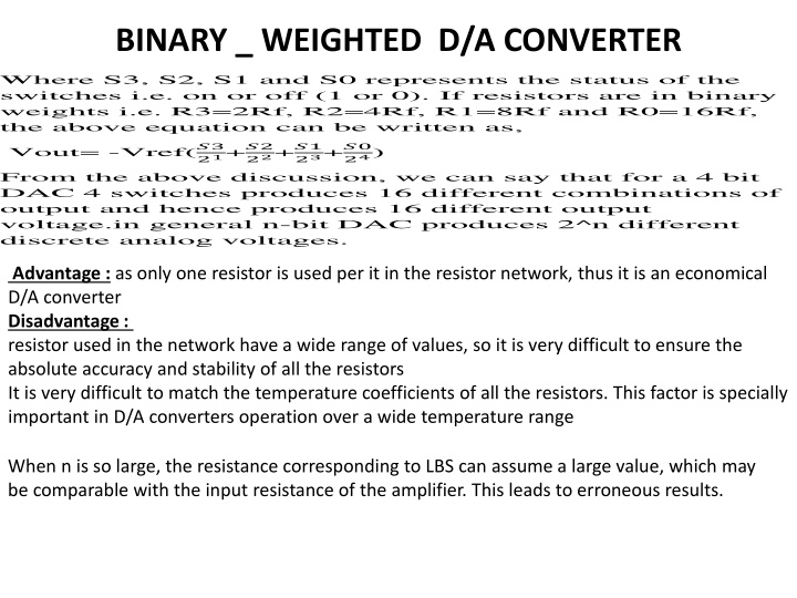
BINARY _ WEIGHTED D/A CONVERTER Where S3, S2, S1 and S0 represents the status of the switches i.e. on or off (1 or 0).If resistors are in binary weights i.e. R3=2Rf, R2=4Rf, R1=8Rf and R0=16Rf, the above equation can be written as, Vout= -Vref(?3 21+?2 22+?1 23+?0 24) From the above discussion, we can say that for a 4 bit DAC 4 switches produces 16 different combinations of output and hence produces 16 different output voltage.in general n-bit DAC produces 2^n different discrete analog voltages. Advantage : as only one resistor is used per it in the resistor network, thus it is an economical D/A converter Disadvantage : resistor used in the network have a wide range of values, so it is very difficult to ensure the absolute accuracy and stability of all the resistors It is very difficult to match the temperature coefficients of all the resistors. This factor is specially important in D/A converters operation over a wide temperature range When n is so large, the resistance corresponding to LBS can assume a large value, which may be comparable with the input resistance of the amplifier. This leads to erroneous results.
R/2R LADDER D/A CONVERTER The bit inputs are switched between V=0 (logic 0) and V=Vref (logic 1).The R 2R network causes these digital bits to be weighted in their contribution to the output voltage Vout. Depending on which bits are set to 1 and which to 0, the output voltage (Vout) will have a corresponding stepped value between 0 and Vref minus the value of the minimal step, corresponding to bit 0. The actual value of Vref (and the voltage of logic 0) will depend on the type of technology used to generate the digital signals.The R 2R ladder is inexpensive and relatively easy to manufacture, since only two resistor values are required (or even one, if R is made by placing a pair of 2R in parallel, or if 2R is made by placing a pair of R in series). It is fast and has fixed output impedance R. The R 2R ladder operates as a string of current dividers, whose output accuracy is solely dependent on how well each resistor is matched to the others. Small inaccuracies in the MSB resistors can entirely overwhelm the contribution of the LSB resistors.
R/2R LADDER D/A CONVERTER For digital value val of a R-2R D/A with N bits and 0V/Vref the output voltage Vout: Vo=Vr*??? 2? If N=5(2?=32) and Vref=3.3 Vo=3.3*31 25=3.19 V With steps Vo=3.3*1 25=0.103 V Advantages: Only two values of resistors are used ( R, 2R) R-2R ladder network are available in monolithic chips. These are laser trimmed to be within 0.01% of the desired ratios
BINARY _ WEIGHTED D/A CONVERTER The following fig. shows the circuit diagram of weighted resistor D/A. This D/A circuit uses weighted values of resistor like 2R,4R,6R,8R and so on depending on the digital inputs available therefore such type of network is known as weighted resistor D/A. This circuit consists of a transistor switch which turns on the switch when the digital input is 1 and if digital input becomes 0 it will open the switch. When transistor switch gets closed, current flows through the weighted resistor due to the reference voltage as shown in circuit diagram. When all such currents from different weighted resistors get added at summing point (which is also known as a virtual ground) of the operational amplifier it will produce a proportional voltage as its output. For 4-bit D/A Vout is Vout=Vref(S3*?? ?3+S2*?? ?2+S1*?? ?1+S0*?? ?0)