Digital vs Analog Communication Advantages, Disadvantages, and Resources
Explore the advantages and disadvantages of digital vs analog communication, including increased immunity to noise, flexibility, encryption for security, and error detection. Learn about channel bandwidth and how Shannons Channel Capacity Theorem applies. Discover basic communication elements and different types of receivers in communication systems.

Download Presentation

Please find below an Image/Link to download the presentation.
The content on the website is provided AS IS for your information and personal use only. It may not be sold, licensed, or shared on other websites without obtaining consent from the author. If you encounter any issues during the download, it is possible that the publisher has removed the file from their server.
You are allowed to download the files provided on this website for personal or commercial use, subject to the condition that they are used lawfully. All files are the property of their respective owners.
The content on the website is provided AS IS for your information and personal use only. It may not be sold, licensed, or shared on other websites without obtaining consent from the author.
E N D
Presentation Transcript
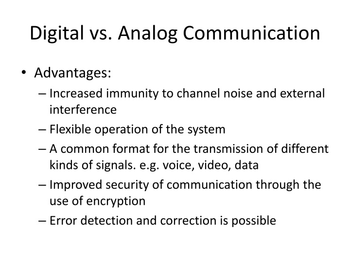
Digital vs. Analog Communication Advantages: Increased immunity to channel noise and external interference Flexible operation of the system A common format for the transmission of different kinds of signals. e.g. voice, video, data Improved security of communication through the use of encryption Error detection and correction is possible
Digital vs. Analog Communication Disadvantages: Increased transmission channel bandwidth Solution Satellite, optical fiber Increased system complexity Solution VLSI, ULSI Note: Although there is no noise & interference on channel the transmitted signal received at the receiver will not be same due to the channel imperfection & non linearity of the channel.
Resources in Communication System Channel Bandwidth Average transmitter power
Shannons Channel Capacity Theorem C = B log2(1 + SNR) bits/sec Where, B = Channel Bandwidth C = Channel Capacity Channel Capacity maximum rate at which the information may be transmitted without error through the channel
Basic Communication Elements (t ) m m(t) s(t) r(t) Signal Processing Carrier Circuit Transmissio n Media Signal Processing Carrier Circuit Transmitter Receiver Noise
Super Heterodyne Type AM Receiver RF carrier range = 535KHz to 1605KHz Mid Band Frequency of IF Section = 455 KHz If Bandwidth = 10KHz Tuning range of Local Oscillator = 80KHz to 1150KHz and 990KHz to 2105KHz Reception of double signal Image frequency between RF Section and Mixer fIF = fRF fLO Selective state required
Super Heterodyne Type FM Receiver Limiter Discriminator Loudspeaker De-emphasis network Audio Amplifier RF carrier range = 88MHz to 108MHz (VHF Band) Mid Band Frequency of IF Section = 10.7 MHz If Bandwidth = 200KHz De-emphasis is used to compensate the pre-emphasis network at transmitter side Pre-emphasis is used to improve SNR
Modulation Modulation is the process by which some parameter of carrier signal is varied in accordance with a modulating signal (message signal) Carrier Signal: Band pass signal Modulating Signal: Base band signal
Types of Modulation Analog Modulation (AM) Angle Modulation Frequency Modulation (FM) Phase Modulation (PM) Digital Modulation (Base band Modulation) Amplitude Shift Keying (ASK) Frequency Shift Keying (FSK) Phase Shift Keying (PSK)
Amplitude Modulation (AM) The amplitude of carrier signal is varied linearly with modulating signal. Standard Form: s(t) = Ac [1 + kam(t)]cos2 fct ka : Amplitude sensitivity of modulator Envelope: a(t) = Ac [1 + kam(t)]
Amplitude Modulation (AM) Case 1: |kam(t)| 1; Percentage Modulation = |kam(t)|*100% = less or equal to 100% Case 2: |kam(t)|> 1; Percentage Modulation > 100% Receiver complexity increases Phase reversal; envelope distortion Over modulation
(a) Intelligence or modulating signal (b) Lower sideband (c) Carrier signal (d) Upper sideband (e) Composite AM wave
Amplitude Modulation (AM) Transmission Bandwidth: 2fm Transmitted Power: Pcarrier + PUSB + PLSB Pcarrier: Ac2 PUSB: 2Ac2 PLSB: 2Ac2 Modulation Factor, = kaAm 1 8 1 8
v v = max min v v + max min
Generation of AM Square Law Modulator Switching Modulator
Square Law Modulator Unwanted signal are removed by tuned band pass filter of Mid Band Frequency = fc Bandwidth = 2fm fc > 3fm
Switching Modulator Unwanted signal are removed by tuned band pass filter of Mid Band Frequency = fc Bandwidth = 2fm fc > 2fm
Detection/Demodulation of AM Square Law detector Envelope Detector
Square Law Detector After LPF, wanted component can be detected
Envelope Detector RsC << 1/fc ; charging time should be less compared to carrier time. 1/fc << RLC << 1/w ; discharging time constant is larger than charging time constant
DSB-SC Time domain s(t) = c(t).m(t) = Accos(2 fct).m(t) Modulated signal undergoes a phase reversal whenever the message signal crosses zero. (due to absence of carrier signal on modulated wave) AcM(0)
DSB-SC Generation Balanced Modulator Ring Modulator/Lattice or Double Balanced Modulator
Balanced Modulator s1(t) = Ac [1 + kam(t)]cos2 fct s2(t) = Ac [1 - kam(t)]cos2 fct s(t) = s1(t) - s2(t) = 2kaAcm(t)cos2 fct
Ring Modulator Required term can be filtered out by using BPF of Mid Band Frequency = fc Bandwidth = 2fm fc > fm
Detection of DSB-SC Coherent Detection/Synchronous detection Costas Loop
Coherent Detection of DSB-SC s(t) = m(t) cos2 fct Product Modulator Low Pass Filter Vo(t)= cos( ).m(t) s(t) = m(t) cos(2 fct + ) Local Oscillator After LPF, Vo(t)= cos( ).m(t) When = 900; Vo(t)= 0 Quadrature Null effect
Costas Loop I - Channel cos( ).m(t) Product Modulator Low Pass Filter cos(2 fct + ) Phase VCO Discriminator s(t) = Acm(t) cos2 fct -900 Phase Shifter sin(2 fct + ) Product Modulator Low Pass Filter sin( ).m(t) Q - Channel
Quadrature Carrier Multiplexing (QAM) Bandwidth conservation scheme Enables two DSB-SC modulated wave to occupy the same transmission bandwidth To maintain the synchronization QAM sends a pilot signal out side the pass band.
QAM Transmitter + Product Modulator Low Pass Filter m1(t) Multiplexed signal + Accos2 fct Local Oscillator -900 Phase Shifter Acsin2 fct Product Modulator m2(t)
QAM Receiver Product Modulator Low Pass Filter m1(t) Accos2 fct Local Oscillator s(t) -900 Phase Shifter Acsin2 fct Product Modulator Low Pass Filter m2(t)
1. In a certain modulation system, the demodulation index is halved when the modulating frequency is doubled keeping the modulating voltage the same. The modulation system is a. AM b. FM c. PM d. PWM Ans: b
2. The line coding technique used in E1 digital stream is a. AMI [DS1, E1] b. NRZ c. HDB3 [E1] d. CMI Ans: c B8ZS [DS1/T1] Polar Biphase:Manchester and Diff. Manchester [802.3 Ethernet LAN, 802.5 Token Ring LAN]
3. If sampling time is less than the Nyquist Interval, then: a. Bandwidth increases b. Channel Capacity Increases c. Guard Time Reduces d. Simpler filters may be used to obtain the original signal Ans: c (check)
4. FM broadcast band lies in a. VHF band [30-300MHz] b. UHF band [300-3000MHz] c. SHF band [3-30GHz] d. HF Band [3-30MHz] Ans: a
5. The number of voice frequency channels in E1 PCM line is a. 16 b. 24 [T1] c. 30 [E1] d. 64 Ans: c
6. The transmission rate of STM 1 in optical fiber is: a. 155.52 Mb/s b. 2.048 Mb/s [E1] c. 140 Mb/s [PDH; E1 Hierarchy, E4 = 139.264 Mb/s] d. 1.54 Mb/s [T1] Ans: a STM-4: 622 Mb/s STM-16: 2.4 Gb/s E3: 34 Mb/s
7. Total voice chnnels avaiable in one PCM link of E1 standard: a. 24 channels [T1] b. 22 channels c. 30 channels [E1] d. 32 channels [E1; total channles] Ans: c
8.Line Coding technique used in 34 Mb/s digital stream is: a. PSK b. AMI c. CMI d. HDB3 [E1; E3 = 34 Mb/s] Ans: d
9. Which of the following modulation techniques has low out-of band spurious radiation? a. QAM b. PSK c. FSK d. MSK Ans: d
GMSK GMSK has a main lobe 1.5 times that of QPSK GMSK<MSK<QPSK Theoretical Bandwidth efficiency limits MSK 1 bit/second/Hz BPSK 1 bit/second/Hz QPSK 2 bits/second/Hz 8PSK 3 bits/second/Hz 16 QAM 4 bits/second/Hz 32 QAM 5 bits/second/Hz 64 QAM 6 bits/second/Hz 256 QAM 8 bits/second/Hz OFDM >10 (depends on the type of modulation and the no. of subcarriers) GMSK 1.35 FSK <1 (depends on modulation index)
10. Which modulation technique occupies least spectral bandwidth? a. QPSK b. BPSK c. 16QAM d. 64QAM Ans: d
11. A band limited signal of fm Hz can be represented without losing any information by its samples uniformly separated at or less than a. 2fm sec b. 1/2fm sec [fs=2fm] c. 2/fm sec d. fm/2 sec Ans: b
12. Which of the following digital modulation system is more resistant to the noise? a. ASK b. FSK c. PSK d. All of above Ans: c PSK>FSK>ASK
13. Which one of the following helps to reduce the qunatizing noise in Pulse Code Modulatioin? a. Higher Sampling Rate b. Lower Sampling Rate c. Higher number of quantizing levels d. Lower number of qunatizing levels Ans: c


")
")
")
 Intelligence or")


")