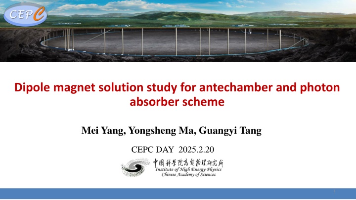
Dipole Magnet Solution Study for Antechamber and Photon Absorber Scheme
Explore the detailed study on dipole magnet solutions for an antechamber and photon absorber scheme in CEPC, focusing on structure modifications, coil designs, and insulation considerations to enhance field quality and power efficiency.

Download Presentation

Please find below an Image/Link to download the presentation.
The content on the website is provided AS IS for your information and personal use only. It may not be sold, licensed, or shared on other websites without obtaining consent from the author. If you encounter any issues during the download, it is possible that the publisher has removed the file from their server.
You are allowed to download the files provided on this website for personal or commercial use, subject to the condition that they are used lawfully. All files are the property of their respective owners.
The content on the website is provided AS IS for your information and personal use only. It may not be sold, licensed, or shared on other websites without obtaining consent from the author.
E N D
Presentation Transcript
Dipole magnet solution study for antechamber and photon absorber scheme Mei Yang, Yongsheng Ma, Guangyi Tang CEPC DAY 2025.2.20 1
Content Content Layout of Collider dipole and vacuum chamber with antechamber and SR absorber Dipole magnet design study Conclusion
Dual aperture dipole in CEPC Collider DAD in TDR VC in TDR Lead width=25mm Coil size: 60*27mm, 2 turns 350 170 25 49 46 61 VC with antechamber Cooling for absorber 3
Structure of vacuum chamber with absorbers Photon absorber size (by Yongsheng Ma) ~ every 5m with an absorber in arc dipoles 220mm in length, 70mm in width (49mm in TDR) Lead around photon absorber(by Guangyi Tang) Absorbed dose increased by 550% Lead width increased to 38mm (25mm in TDR) Lead length is about 440mm 70mm Width increase for VC+Lead ~ 34mm in one aperture near the center yoke 17mm 4
Dipole magnet design study Narrow coil width: reduced from 60mm to 40mm(40*27mm) Current remains the same, current density increases from 1.1A/mm2to 1.6A/mm2 52% increase in Power P 8MW @ ttbar) Field quality changes can be acceptable. Lead, dep=38mm Space for trim coil Main coil: 40*27mm, 2 turns 5
Dipole magnet design study -2 Slim coils embedded in yoke: large height narrow width (40mm*37mm*2) Thickness of yoke reduced by 22%, weak yoke, increase the yoke machining 10% increase in Power, ~1.5MW @ttbar Need to evaluate the strength and pole deformation Field harmonics change one unit, the trim coil has not been considered 6
Coil insulation considerations Insulation materials Hard anodizing of aluminum rod Typical voltage withstand range 400~500V @t=20um Edge effect Long stability Thermal spray ceramic coating 1Mpa 30min 500V 280V 1000V 10 A) 985 A (m ) 0.47m 0.54m 0.66m Ceramic spacers Peek/CF 5.7m 7
Conclusions With photon absorber and antechamber in VC, the structure of the magnet should be modified and has little effect on the field quality. The power consumption is increased and the structure of magnet becomes complex with more machining. Severe space constraints may have an impact on magnet mechanical stability of dipole, which should be studied further. With absorber, the adjacent area must stand more radiation heat load should be evaluated, which may require more space for cooling or so. For dipole magnet iron, the concentrated SR load should be evaluated also. 8