Discover Hydraulic Circuit Control Techniques
Explore various hydraulic circuit control circuits such as single-acting hydraulic cylinder control, double-acting cylinder control, regenerative cylinder circuit, and more. Learn how hydraulic circuits are used for power transmission and control in different applications.

Download Presentation

Please find below an Image/Link to download the presentation.
The content on the website is provided AS IS for your information and personal use only. It may not be sold, licensed, or shared on other websites without obtaining consent from the author. If you encounter any issues during the download, it is possible that the publisher has removed the file from their server.
You are allowed to download the files provided on this website for personal or commercial use, subject to the condition that they are used lawfully. All files are the property of their respective owners.
The content on the website is provided AS IS for your information and personal use only. It may not be sold, licensed, or shared on other websites without obtaining consent from the author.
E N D
Presentation Transcript
Introduction A hydraulic circuit is a group of components including one or more pump, actuators, valves, piping, and ancillary equipment. It is used for power transmission and control. Hydraulic Valve F x v v Hydraulic Cylinder V x I T x Electric Motor Hydraulic Pump T x P x Q Hydraulic Motor
Hydraulic Circuits Single Acting Hydraulic Cylinder Control Circuit Double Acting Hydraulic Cylinder Control Circuit Regenerative Cylinder Circuit Pump Unloading Circuit Double Pump Circuit Counterbalance Valve Circuits Cylinder Sequencing Circuits Locked Cylinders using Pilot Check Valves Cylinder Synchronization Circuits Fail Safe Circuits
Single Acting Hydraulic Cylinder Control Circuit Analysis Objectives Given: Load carrying capacity Extension speed Retraction speed What are the objective of design analysis?
Single Acting Hydraulic Cylinder Control Circuit Analysis Objectives Pump Pressure Relief Valve Cracking pressure Full Open pressure Size Spring Stiffness Initial Compression Flow rate Pressure Head Type
Single Acting Hydraulic Cylinder Control Circuit Design Optimization What are the objective of design optimization?
Single Acting Cylinder Control Circuit Design Optimization Improve efficiency (operating cost) Reduce size and weight Increase safety Reduce cost Simplify operation Improve functionality Allow to stop during stroke Allow servo control Increase retraction speed .. Extend working life Reduce noise Improve reliability Reduce pollution and environmental effects
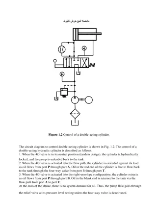
Double Acting Cylinder Control Circuit Extend Hold Retract
Double Acting Cylinder Control Circuit Hold Retract Extend
Automatic Cylinder Reciprocating System Two sequence valves sense a stroke completion by corresponding buildup of pressure. Each check valve and corresponding pilot line prevents shifting of the directional control valve until the particular stroke of the cylinder has been completed. 0.00 Bar 0.00 Bar 0.00 Bar The check valves are needed to allow pilot oil to leave either end of the DCV while pilot pressure is applied to the opposite end. This permits the spool of the valve to move as required.
Flow and pressure analysis in the automatic reciprocating cylinder During the extension stroke, the speed of the piston is determined by the flow rate out of the pump, and the area of the blank-end of the piston. Q v Q A v = = , A P b pump P pump b Assuming constant piston speed, and resistive load on the piston, (load resisting the extension), the pressure on the rod end of the piston (gauge pressure) is equal to the pressure loss in the return line connecting the outlet port to the tank. laminar , Q K p pipe r = = flow 2 turbulent , flow p K Q r pipe f is the friction factor for the pipe. For fully turbulent flow, f is a function of the pipe s relative roughness. In the transition region, f is a function of the relative roughness and Re. It is determined from the Moody diagram. For a straight circular pipe, the pipe flow coefficient, K pipe is: ( ( turbulent , 8 D L f K pipe = ) ) = 4 128 laminar , flow K L D pipe 2 5 flow
Flow and pressure analysis in the automatic reciprocating cylinder The pressure on the blank end is determined by the pressure on the rod side and the load = + p A = p A F b b r r load + ( ) p p A A F A b r r b load b
Regenerative Circuit One characteristic of the double acting cylinder circuit is that the extension speed is always lower than the retraction speed. Fload Can you think with design modification to the circuit to make the extension speed equal to the retraction speed?
Regenerative Circuit Fload Fload
Regenerative Circuit A regenerative circuit is used to speed up the extension speed of the piston in a double-acting hydraulic cylinder. Note that the pipelines to both ends of the hydraulic cylinder are connected in parallel, and that one of the ports in of the four-way valve is blocked. Fload The operation of the cylinder during the retraction stroke is the same as that of a regular double-acting cylinder. In this mode, fluid from the pump bypasses the DCV and enters the rod side of the cylinder. Fluid in the blank side drains back to the tank through the DCV as the cylinder retracts
Double Pump Hydraulic System
Double Pump Hydraulic System A high-pressure, low-flow pump works in conjunction with a low- pressure, high-flow pump. A typical application is a sheet metal punch where high force and pressure requirements occur during a short motion portion of the hydraulic cylinder when the punching operation occurs. 0.00 Bar During the punching operation, the cylinder travel is small, and thus the flow-rate requirements are low. The circuit eliminates the necessity of having a very expensive high pressure, high flow pump Low Flow Pump High Flow Pump 24.00 LPM 630.00 LPM
Double Pump Hydraulic System Before the punching operation begins, the rapid extension of the piston is provided by both pumps operating at low pressure outlet (pressure is determined by the load). The flow of the high-flow pump goes through the check valve to the hydraulic cylinder. 0.00 Bar Near the end of the cylinder stroke the punching operation begins and the increased pressure opens the unloading valve to unload the high- flow pump. The check valve protects this pump from the high pressure generated by the high-pressure pump. Low Flow Pump High Flow Pump 24.00 LPM 630.00 LPM
Analysis of a Double Pump Circuit The gauge pressure on the rod end of the piston is equal to the pressure loss in the return line connecting the outlet port to the tank. = = + p A = p A F b b r r load + ( ) p p A A F A b r r b load b 0.00 Bar laminar , flow p K Q , r ext pipe = 2 turbulent , flow p K Q , r ext pipe Low Flow Pump High Flow Pump 24.00 LPM 630.00 LPM During the rapid extension, the flow rate is high and the rod-end pressure will be significant. The blank-end pressure, pb,extis given by: p p , , = During the punching operation, the flow rate is small, and the rod-end pressure is negligible. The blank-end pressure is determined by the punching load: F p = , ( ) A A b ext r ext r b A The pressure calculated above may be used to determine the settings of the unloading valve, ps,uv . For example, we could set it to be equal to 1.5 times pb,ext b punch punch b The pressure calculated above may be used to determine the settings of the pressure relief valve, ps,rv . For example, we could set it to be equal to 1.5 times pb,punxh
Protection from Inadvertent Cylinder Extension The circuit utilizes a pilot operated check valve to prevent the cylinder from falling in the event of hydraulic line rupture or pump failure. The valve also provides protection in case someone inadvertently operates the manual override on the pilot actuated directional control valve when the pump is not operating.