DOE Webinar Sound Options & Topics
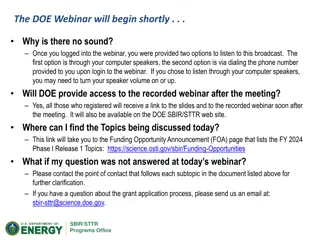
The DOE Webinar provides sound options and discusses FY 2021 Phase I Release 2 Topics. Access to the recorded webinar will be available post-meeting. For unanswered questions, contact the provided points of contact for further clarification or email sbir-sttr@science.doe.gov. Explore the agenda, schedule, and participating DOE programs in the Funding Opportunity Announcements for Phase I Releases 1 and 2.

Download Presentation

Please find below an Image/Link to download the presentation.
The content on the website is provided AS IS for your information and personal use only. It may not be sold, licensed, or shared on other websites without obtaining consent from the author.If you encounter any issues during the download, it is possible that the publisher has removed the file from their server.
You are allowed to download the files provided on this website for personal or commercial use, subject to the condition that they are used lawfully. All files are the property of their respective owners.
The content on the website is provided AS IS for your information and personal use only. It may not be sold, licensed, or shared on other websites without obtaining consent from the author.
E N D
Presentation Transcript
Chapter III Frequency response analysis 1. Experimental system characterization 2. Nyquist stability analysis 3. Compensators 4. PID tuning a. PID structure b. Ziegler Nichols 1 c. Ziegler Nichols 2 d. Cohen Coon Automatic Control 211 ASU MN Sabry 2021 III.4 1
PID structure Kp R E C + G KI / s KD s + ++ May not be entirely known Proportional part Kp: High signal for high E; small effect when E 0 High signal if E persists with time; may increase overshoot Integral part KI=Kp/TI: High signal if E increases with time; phases out when E is decreasing Derivative part KD=KpTD: You may deactivate any part PI only is very common Automatic Control 211 ASU MN Sabry 2021 III.4 2
Ziegler Nichols 1 For systems exhibiting NO oscillation for open-loop operation: 1.2 c (t) 1 ) ( ( ) ( ) ( ) t T T t T 1 c t K e delay 0.8 T delay c0 = K u0 0.6 0.4 u T c T u (t) T = = 0 K Tdelay 0 0.2 KT u0 0 delay delay 0 0 2 4 6 8 KP K0 TI TD Type of controller P PI PID 0.9 K0 1.2 K0 Tdelay/0.3 2 Tdelay Tdelay/2 Automatic Control 211 ASU MN Sabry 2021 III.4 3
Ziegler Nichols 2 For systems exhibiting oscillation for closed-loop operation: 8 K = Kcr Adjust controller gain K to obtained sustained oscillation (Neither decay nor grow) K is small K is large 6 4 2 time 0 0 2 4 6 8 10 12 Kcr( 2K0) Pcr ( 4Tdelay) Required gain: Associated period: -2 -4 -6 -8 KP TI TD Type of controller P PI PID (Kcr/2) 0.9 (Kcr/2) 1.2 (Kcr/2) (Pcr/4)/0.3 2 (Pcr/4) (Pcr/4)/2 Automatic Control 211 ASU MN Sabry 2021 III.4 4
Cohen Coon Replaces Ziegler Nichols 1 for large Tdelay: delay T T u T c T T = = 0 = K R 0 KT 0 delay delay KP TI TD Type of controller K R + 01 P 3 K R + 30 3 9 20 + R R + 00.9 delay T PI 12 + + 32 6 13 8 + R R 4 + 16 3 12 R PID delay T delay T K 0 11 2 R Automatic Control 211 ASU MN Sabry 2021 III.4 5
Fine tuning guidelines Effects of increasing a parameter independently* Settling time Small change Increase Steady- state error Parameter Rise time Overshoot Stability Decrease Increase Decrease Degrade KP Decrease Minor change Increase Eliminate No effect in theory Degrade Improve if KDsmall KI Decrease Decrease KD * Kiam Heong Ang; Chong, G.; Yun Li (2005). "PID control system analysis, design, and technology". IEEE Transactions on Control Systems Technology. 13 (4): 559 576. doi:10.1109/TCST.2005.847331. S2CID 921620. Automatic Control 211 ASU MN Sabry 2021 III.4 6