DTF Modules Planning Guide
Discover a comprehensive guide on setting out DTF modules, including layout plan, longitudinal profile, levels, and procedure for Oloolaiser DTF. Learn how to mark positions accurately and ensure successful implementation while considering cost implications.

Uploaded on | 2 Views
Download Presentation

Please find below an Image/Link to download the presentation.
The content on the website is provided AS IS for your information and personal use only. It may not be sold, licensed, or shared on other websites without obtaining consent from the author. If you encounter any issues during the download, it is possible that the publisher has removed the file from their server.
You are allowed to download the files provided on this website for personal or commercial use, subject to the condition that they are used lawfully. All files are the property of their respective owners.
The content on the website is provided AS IS for your information and personal use only. It may not be sold, licensed, or shared on other websites without obtaining consent from the author.
E N D
Presentation Transcript
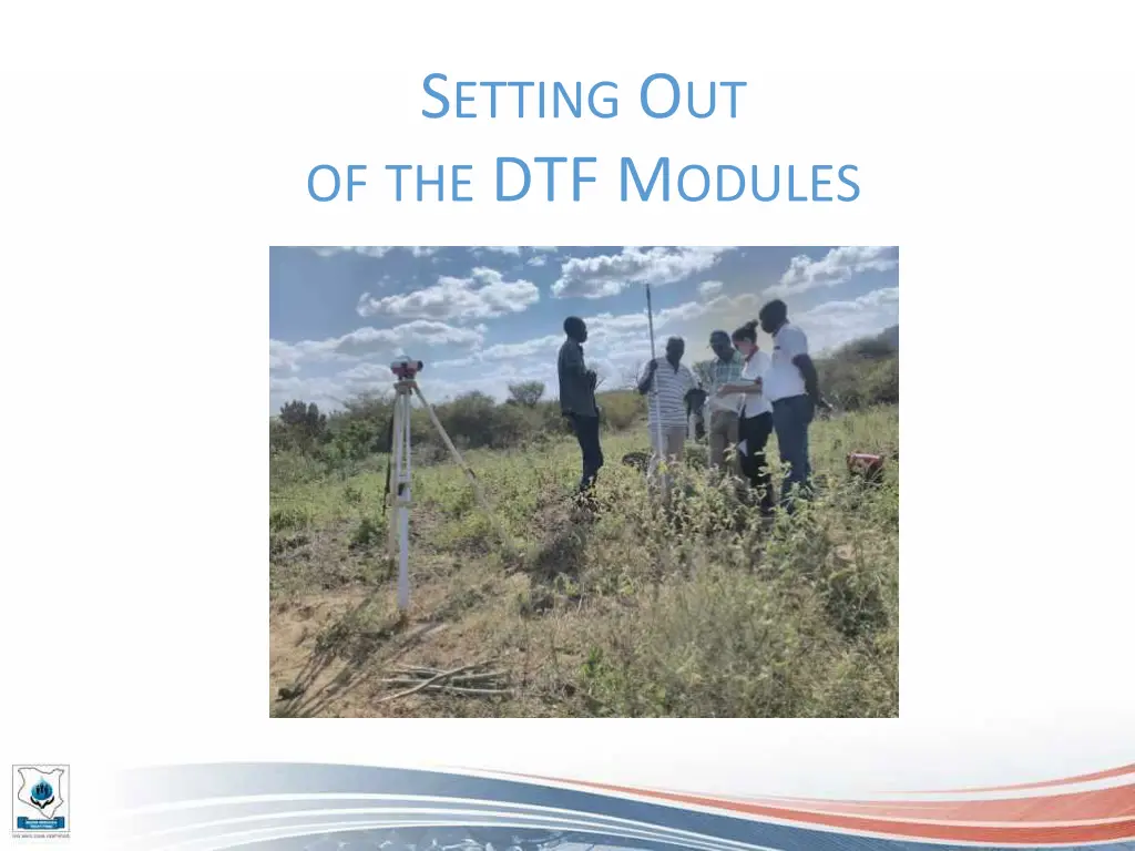
SETTING OUT OFTHE DTF MODULES
LONGITUDINAL PROFILE < 1% < 1% < 10% 0.8m 1m 0.1m 0.6m
LEVELS < 1% < 1% < 10% 0.8m 1m 0.1m 0.6m Module inlet Distances [m] Minimum level difference [m] 5 0.8 + 0.05 = 0.85 Inlet RBBT and Inlet Settler 1 1 + 0.1 = 1.1 Inlet Settler and inlet ABR Inlet ABR and Inlet VFCW 20 1 + 0.2 = 1.2 Inlet VFCW and Water body 450 4.5
PROCEDURE (in the case of Oloolaiser DTF) 1. Mark the position of the first module RBBT with pegs (on the 4 corners), using the distances from the layout plan 2. Mark the position of the Settler using the distances from the layout plan and double checking the expected level from the longitudinal profile 3. Same way: mark the position of the ABR (distances double checked with levels) 4. Same way mark the position of the VFCW (distances double checked with levels) 5. Mark the position of the SDB, the Operator Store and the incinerator using the layout plan (levels not as important as with the rest of the modules) Remember: the BoQ has been done according to the initial setting out. Changing the setting out might lead to a variation in costs (excavation)


")