Dynamic Systems Analysis in Automatic Control
This content delves into constructing system models, solving system equations, understanding standard systems, and analyzing system performance. It covers physical systems, connections, potentials, and flows, as well as equation types such as conservation and constitutive equations. Object types like static, dynamic, resistive, capacitive, inductive, thermal, electric, and mechanical are explored in detail.

Download Presentation

Please find below an Image/Link to download the presentation.
The content on the website is provided AS IS for your information and personal use only. It may not be sold, licensed, or shared on other websites without obtaining consent from the author.If you encounter any issues during the download, it is possible that the publisher has removed the file from their server.
You are allowed to download the files provided on this website for personal or commercial use, subject to the condition that they are used lawfully. All files are the property of their respective owners.
The content on the website is provided AS IS for your information and personal use only. It may not be sold, licensed, or shared on other websites without obtaining consent from the author.
E N D
Presentation Transcript
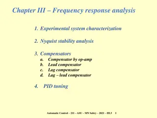
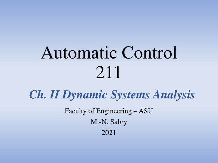
Automatic Control 211 Ch. II Dynamic Systems Analysis Faculty of Engineering ASU M.-N. Sabry 2021
Chapter II Contents 1. Constructing system models a. Fluxes, potentials and object models b. System equations Examples 2. Solving system equations 3. Standard systems 4. System performance Automatic Control 211 ASU MN Sabry 2021 II.1.a 2
Physical systems: Objects & Connections + External relations Objects Connections Material System Material: Sources Passive elements - Mass - Momentum - Energy - Charge - ... Transforms or transfers material Adds or absorbs material Automatic Control 211 ASU MN Sabry 2021 II.1.a 3
Connections: Potentials & Flows At each connection (or node ): - Flux of material quantities (in or out of the object) - Under the action of a potential difference (between connections) Potential difference P P or Across quantity or Intensive property Flux F F Material quantity M M or Trough quantity or Extensive property m Mass flow rate or volumetric discharge Pressure difference P Mass m or volume V V Electric potential difference V Electric charge Q Electric current I Displacement difference x or Velocity difference v Temperature difference T Momentum M Force F Q Internal energy U Heat flux Automatic Control 211 ASU MN Sabry 2021 II.1.a 4
Equation types Conservation equations + = d dt General form: F F S M in out Input flux Output flux Rate of accumulation Source I F + = m m + reaction m dQ = d m dt = = dt Mass balance: Charge balance: in out I dM = ( Q system = F I ionic system dt ) W dyn Momentum balance: system inertia + Q dU dt Energy balance: prod system Constitutive (model) equations General form: (see below) f(Fi, dFi/dt, Pi, dPi/dt) = 0 Fi, Pi: Flux and potential at object nodes i Automatic Control 211 ASU MN Sabry 2021 II.1.a 5
Object types: 1) Static & dynamic F = P / R A. Resistive or static: General form: Viscous Friction: = = v viscous F C I V R = Electric: Q T R Thermal: elec therm F = C d P / dt General form: B. Capacitive (dynamic): = v F md dt = = Electric: Thermal: Q Mech: CdT dt I CdV dt A dV dh dt system dt = = = = Fluid tank: ; h Q Q Q A P gh net in out m m in out F = C P dt C. Inductive (dynamic): General form: ( ) = = = v F k x k dt Electric: Spring: 1 I L V dt Automatic Control 211 ASU MN Sabry 2021 II.1.a 6
Object types: 2) Transducers & Sources Transducer Potential source Potential = Const. Flux Physical Domain A Physical Domain B ~ System Ideal transducer: Power in = Power out Power = Flux . Potential Flux source Flux = Const. Electric power = Current . Volt Potential Mech. linear power = Force . Velocity Mech. rotational power = Torque . Rot. velocity Fluid power = Discharge . Pressure System Sources can be electric, thermal, fluid, mechanical Automatic Control 211 ASU MN Sabry 2021 II.1.a 7
Object types: 3) Op-Amp function Loading effect on previous system: Direction of signal flow is +ve Loading effect on next system: energy Actuator Controller energy Hot Body To actuate any system: - Energy is extracted - Previous system state is altered (undesirable) let previous system has its own energy source To measure any system: - Energy is extracted - Its state is altered (undesirable) let energy extracted ~ 0 Operational Amplifier Op - Amp energy ~ 0 Eamp Op- Amp + Energy out can be anything Eout But no effect on Eout Automatic Control 211 ASU MN Sabry 2021 II.1.a 8
Op Amp model Charge balance at A: IZ1 = IZ2 + Iamp High amplifier gain K (~106): Eout = K Eamp IZ2 Z2 IZ1 Iamp Z1 A Op- Amp + Approximation 1: Eamp = Eout / K ~ 0 Ein Eamp Eout Approximation 2: Iamp~ 0 IZ1 = (Ein 0) / Z1 = IZ2 = (0 Eout) / Z2 Eout/ Ein = Z2 / Z1 Automatic Control 211 ASU MN Sabry 2021 II.1.a 9


 Static & dynamic")
 Transducers & Sources")
 Op-Amp function")