Early Stages of Inertial Confinement Fusion Implosions
Explore the perturbation evolution at the early stages of inertial confinement fusion implosions, including the identification of a new instability in low-adiabat designs. Learn about nested rarefaction waves, shock characteristics, and post-shock flow dynamics affecting shell behavior. Gain insights into drive conditions and target design choices to mitigate instabilities in fusion experiments.

Download Presentation

Please find below an Image/Link to download the presentation.
The content on the website is provided AS IS for your information and personal use only. It may not be sold, licensed, or shared on other websites without obtaining consent from the author. If you encounter any issues during the download, it is possible that the publisher has removed the file from their server.
You are allowed to download the files provided on this website for personal or commercial use, subject to the condition that they are used lawfully. All files are the property of their respective owners.
The content on the website is provided AS IS for your information and personal use only. It may not be sold, licensed, or shared on other websites without obtaining consent from the author.
E N D
Presentation Transcript
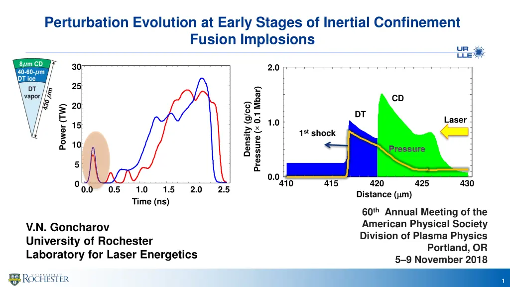
Perturbation Evolution at Early Stages of Inertial Confinement Fusion Implosions 30 2.0 25 Pressure ( 0.1 Mbar) CD 20 Density (g/cc) Power (TW) DT Laser 1.0 15 1st shock 10 Pressure 5 0.0 410 415 420 425 430 0 0.0 0.5 1.0 1.5 2.0 2.5 Distance ( m) Time (ns) 60th Annual Meeting of the American Physical Society Division of Plasma Physics V.N. Goncharov University of Rochester Laboratory for Laser Energetics Portland, OR 5 9 November 2018 1
Summary A new instability of nested rarefaction waves has been identified for low-adiabat, decaying-shock designs A secondary rarefaction wave in the ablator is formed after a decaying shock passes through the ablator fuel interface Created nested rarefaction waves form a local minimum in the flow velocity profile, which leads to hydrodynamic instability; the threshold for the local minimum formation depends on shock strength and ablator thickness Linear stability analysis helps identifying drive conditions and target design choices to mitigate this instability The nested rarefaction instability amplifies imprint and surface roughness/defect growth in the low-adiabat designs and leads to ablator fuel mix* * C. Stoeckl, previous talk, PO4-3 2
An intensity picket at the beginning of the drive creates a decaying shock and outgoing rarefaction CH shell Unsupported (decaying) shock Supported shock 30 Density, Pressure (a.u.) 2 1 Power (TW) 1 20 Shock Laser 2 10 Density Pressure 0 440 444 448 440 444 448 0.0 0.5 1.0 Time (ns) 1.5 2.0 2.5 Distance ( m) 3
Post-shock flow leads to a set of divergent characteristics and decaying perturbations inside the shell Shock front frame of reference 1.0 CH shell driven by a 70-ps, 3-J intensity picket Normalized profiles 0.5 V Cs time Density V+Cs Mass density (g/cm3) 3.0 Rarefaction wave (RW) 0.0 Decaying shock - 0.5 0 10 20 30 40 2.0 Distance ( m) Characteristics Laser 40 ??+ ?? ?? ?? 1.0 = ? + ?? Ablation front Distance ( m) 30 = ? ?? 0.0 20 410 420 430 Distance ( m) 440 450 460 10 Ablation front 0 0.4 0.6 0.8 1.0 1.2 1.4 Time (ns) Shock 4
Post-shock flow leads to a set of divergent characteristics and decaying perturbations inside the shell Shock front frame of reference 1.0 CH shell driven by a 70-ps, 3-J intensity picket Normalized profiles 0.5 V Cs Density V+Cs Mass density (g/cm3) 3.0 0.0 No information flow1 - 0.5 0 10 20 30 40 2.0 Distance ( m) Characteristics Laser 40 ??+ ?? ?? ?? 1.0 = ? + ?? Ablation front Distance ( m) 30 = ? ?? 0.0 20 410 420 430 Distance ( m) 440 450 460 10 0 0.4 0.6 0.8 1.0 1.2 1.4 Time (ns) 1 I. Igumenshchev, UO4.00011, this conference 5
Nested rarefaction waves are created when a material interface is present in the shell Comparison of a decaying shock propagation in a single-material (CH ) and CH-DT shell Picket is on Supported shock Picket is off Decaying shock Secondary RW due to CH/DT Shock in CH Pressure (a.u.) Density (a.u.) Shock Original RW Laser 440 444 448 440 444 448 440 444 448 420 430 440 Distance ( ( m) ) Shock in DT CH DT interface 6
Secondary rarefaction creates a kink in the velocity profile and locally convergent characteristics Characteristics Shock Shock frame of reference 50 Ablation front 1.0 Velocity 40 Density 0.8 Position ( m) Normalized profiles Local minimum Local minimum CH/DT 30 0.6 0.4 20 V+Cs Ablation front 0.2 10 DT CH 0.0 0 10 20 30 40 50 0 Distance ( m) 0.5 1.0 1.5 2.0 Time (ns) 7
Secondary rarefaction creates a kink in the velocity profile and locally convergent characteristics Shock frame of reference 50 1.0 Velocity 40 Density 0.8 Position ( m) Normalized profiles 30 0.6 0.4 20 V+Cs 0.2 10 DT CH 0.0 0 10 20 30 40 50 0 Distance ( m) 0.5 1.0 1.5 2.0 Time (ns) 8
Linear perturbation analysis is used to calculate perturbation growth in the nested rarefactions System of conservation laws for adiabatic flow From 1-D code LILAC Numerical integration ?? ??+ ? ?? = ? ? = ?? ?+ ? ? = ?? ?+ ? ?? ??+ ??? + ???? = ? ??= ??,? ?+ ?? ?? ??= ?? ??+ ??? +?? = ? ? 9
Converging characteristics lead to local steepening in density and subsequent growth in pressure perturbation and vorticity 1.0 1.2 t= =1.3 ns 0.5 Follow 3 characteristics near the local minimum 1.0 Mass density (g/cm3) 0.0 Density 0.8 ? ? + ?? ?? - 0.5 V+Cs ? Normalized profiles 0.6 - 1.0 - 1.5 0.4 32.0 33.0 34.0 1.0 t= =1.8 ns 0.2 0.5 0.0 0.0 0 10 20 30 40 50 - 0.5 Distance ( m) - 1.0 Pressure perturbation growth leads to vorticity generation ???? ? ???/? - 1.5 47.0 48.0 49.0 50.0 Distance ( m) 10
Velocity perturbation grows exponentially in the nested rarefaction waves at the point of local minimum in flow velocity Normalized velocity perturbation 0.20 4 Normalized vorticity 0.10 2 0.05 0 0.02 2 0.01 0.6 0.8 1.0 1.2 1.4 1.6 1.8 0.4 0.6 0.8 1.0 1.2 1.4 1.6 1.8 Time (ns) Time (ns) 11
Reducing intensity decay rate in the picket increases sound speed in the ablator and prevents formation of the local minimum in the flow velocity Velocity ( 106 cm/s) Mass density (g/cm3) Power (TW) DT CH Time (ns) Distance ( 100 m) 12
Summary A new instability of nested rarefaction waves has been identified for low-adiabat, decaying-shock designs A secondary rarefaction wave in the ablator is formed after a decaying shock passes through the ablator fuel interface Created nested rarefaction waves form a local minimum in the flow velocity profile, which leads to hydrodynamic instability; the threshold for the local minimum formation depends on shock strength and ablator thickness Linear stability analysis helps identifying drive conditions and target design choices to mitigate this instability The nested rarefaction instability amplifies imprint and surface roughness/defect growth in the low-adiabat designs and leads to ablator-fuel mix1 1 C. Stoeckl, previous talk, PO4-3 13
Summary Backup slides 14
Fast varying features in a laser pulse and material interfaces in the shell lead to complex hydrodynamics during the early stages of an implosion 2.0 RT-unstable interface 30 Shot # 77070 Pressure ( 0.1 Mbar) Nested rarefaction Density (g/cc) CD Power (TW) 20 1.0 Laser Decaying shock Pressure 10 DT 0.0 410 415 420 425 430 0 0.0 0.5 1.0 Time (ns) 1.5 2.0 2.5 Distance ( m) Nonuniformity seeds are amplified by Rayleigh-Taylor instability during shell acceleration and deceleration 15
Nonuniformity seeds develop during early-time shock propagation through the shell Laser imprint Surface/shell defects and roughness defect t=0 Laser shock Main shock breakout Ablation front Nonuniformity seeds are amplified by Rayleigh-Taylor instability during shell acceleration and deceleration 16
Density (g/cm3), Pressure (0.01 Mbar) 1.2 1.0 Pressure 0.8 0.6 Density 0.4 0.2 0.0 400 410 420 430 440 450 Distance ( m) 17


, Pressure (×0.01 Mbar)")