Electric Circuits: Thevenin & Norton Equivalent Circuits Explained
Understand Thevenin's and Norton's theorems in electric circuits, where linear two-terminal circuits can be simplified using voltage and current sources with respective impedances. Learn how to apply these techniques with examples to find the equivalent circuits between terminals. Explore how to calculate consumed power in impedance connected between terminals using Thevenin's theorem.

Download Presentation

Please find below an Image/Link to download the presentation.
The content on the website is provided AS IS for your information and personal use only. It may not be sold, licensed, or shared on other websites without obtaining consent from the author. If you encounter any issues during the download, it is possible that the publisher has removed the file from their server.
You are allowed to download the files provided on this website for personal or commercial use, subject to the condition that they are used lawfully. All files are the property of their respective owners.
The content on the website is provided AS IS for your information and personal use only. It may not be sold, licensed, or shared on other websites without obtaining consent from the author.
E N D
Presentation Transcript
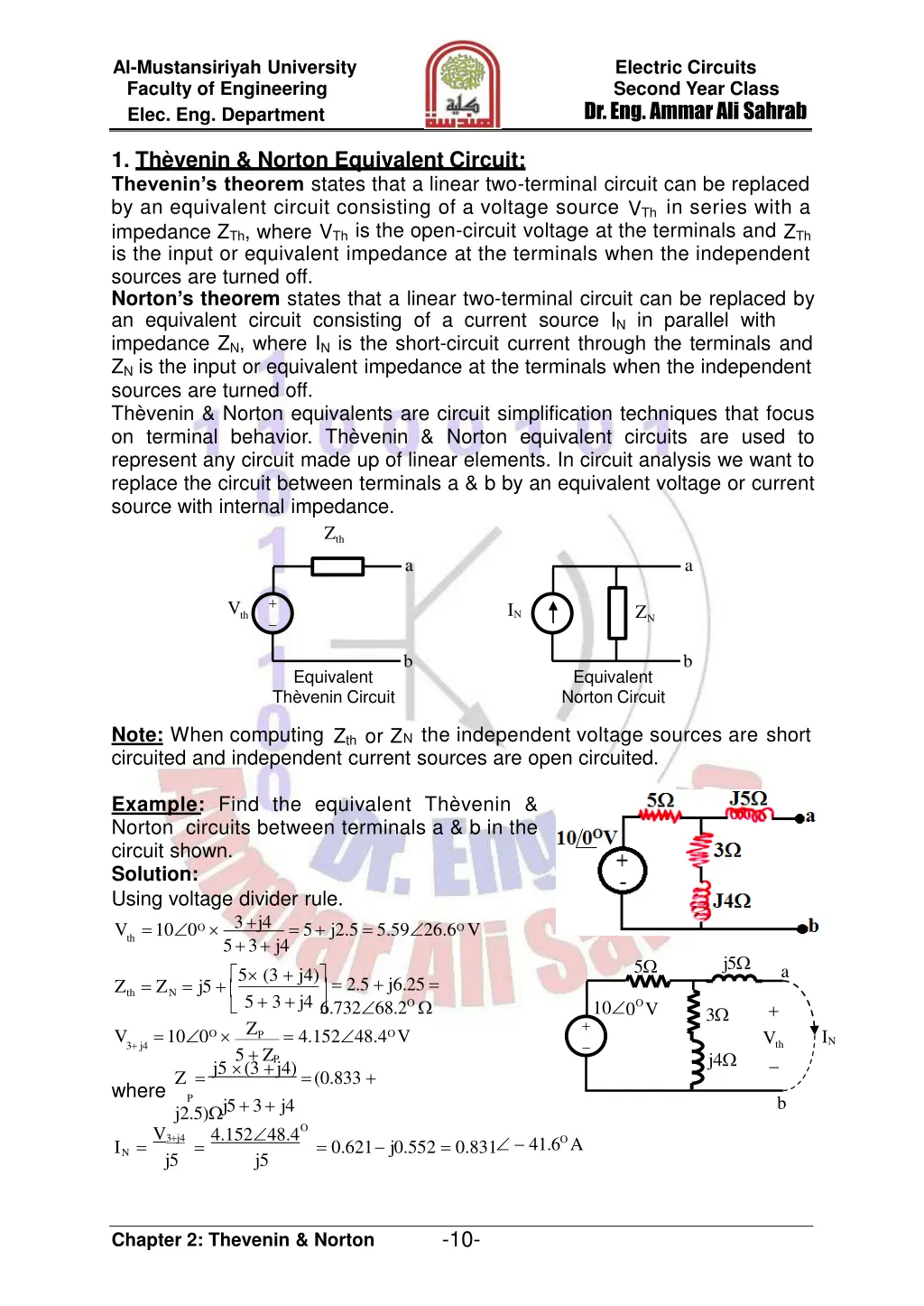
Al-Mustansiriyah University Faculty of Engineering Elec. Eng. Department Electric Circuits Second Year Class Dr. Eng. Ammar Ali Sahrab 1. Th venin & Norton Equivalent Circuit: Thevenin s theorem states that a linear two-terminal circuit can be replaced by an equivalent circuit consisting of a voltage source VThin series with a impedance ZTh, where VThis the open-circuit voltage at the terminals and ZTh is the input or equivalent impedance at the terminals when the independent sources are turned off. Norton s theorem states that a linear two-terminal circuit can be replaced by an equivalent circuit consisting of a current source IN in parallel with impedance ZN, where INis the short-circuit current through the terminals and ZNis the input or equivalent impedance at the terminals when the independent sources are turned off. Th venin & Norton equivalents are circuit simplification techniques that focus on terminal behavior. Th venin & Norton equivalent circuits are used to represent any circuit made up of linear elements. In circuit analysis we want to replace the circuit between terminals a & b by an equivalent voltage or current source with internal impedance. Zth a a + V IN ZN th b b Equivalent Th venin Circuit Equivalent Norton Circuit Note: When computing Zth or ZN the independent voltage sources are short circuited and independent current sources are open circuited. Example: Find the equivalent Th venin & Norton circuits between terminals a & b in the circuit shown. Solution: Using voltage divider rule. V =10 0O th 5+3+ j4 5 (3 + j4) = 2.5 + j6.25 = 6.732 68.2O V =10 0O 3+ j4 5 + ZP Z =j5 (3 + j4)=(0.833 + where P j5+3+ j4 V3+ j4 4.152 48.4 I = = = 0.621 j0.552 = 0.831 N j5 j5 3+j4 = 5+ j2.5 = 5.59 26.6OV j5 5 a Z = Z = j5 + th N 5 + 3 + j4 ZP = 4.152 48.4OV 10 O + 0 V 3 + IN V th j4 b j2.5) O 41.6O A -10- Chapter 2: Thevenin & Norton
Al-Mustansiriyah University Faculty of Engineering Elec. Eng. Department Electric Circuits Second Year Class Dr. Eng. Ammar Ali Sahrab 12 Find the Th venin circuits with & Norton to Example: equivalent terminals a & b for the circuit shown. Solution: and Vth = V20 + V8 respect the 5 8 a + 72V IN + Vth (12 + 8) 5 (12 + 8) + 5 20 = 4 ZP = Using voltage divider rule. V = 72 20 20 + ZP = 60 + 4.8 = 64.8V 5 20 Z'= = 4 P 5 + 20 =12 (8+ZP)= 6 Z = Z th N 12+8+ Z' = I12 + I8 =20 8+5 = P 20 + 8 '' Z =12 ZP =5.66 T 12 + Z'' P I =VT =72 =12.72A T ZT 5.66 Using current divider rule. I = I 12 T Z''+12 P IN = 6 + 4.8 = 10.8A b 20 = 60V and V = (72 8 = 4.8V 8 +12 ) 8 20 V Vth ' P IN Z'' 10.7143 ZP = 6A and I = (I I ) 20 '' 8 T 12 20 + 8 = 4.8A Find the Th venin & Norton Example: equivalent circuits with respect to the terminals a & b for the circuit shown. Solution: ? = 5 30? 20+?10 = 1.58 48.4? (5 + ?5) = 11.18 93.4 ? ? = 5 30? 2.2 56.56 ? (15+?5)(5+?5) 20+?10 = ? = Another way: 5 3 0 ?? = 5+?5= 1.58 48.4 ? ?? 5+?5 = 15+?5 = 4 + ?3 = 5 36.87 ? 5+?5 = 11.18 93.4 ? ? ? ( 5 + ?5 ) 20+?10 ????? ???? ??? ????? 11.18 93.4? 5 36.87? ?=? = ?? = 2.2 56.56 ? ? -11- Chapter 2: Thevenin & Norton
Al-Mustansiriyah University Faculty of Engineering Elec. Eng. Department Electric Circuits Second Year Class Dr. Eng. Ammar Ali Sahrab Example: Find the consumed power in (2+j4) impedance connected between terminals a & b using Th venin theorem for the circuit shown. Solution: 100 0 60 90 100 ?60 = = = 100 0? (3 + ?4)(14.46 38.1 ) = 124.6 35.46 ? = (3 + ?4)//(5 ?5) = 4.22 + ?1.14 = 4.38 15.2 ?? = 15.44 75 ? ?= = +2+?4 6.22+?5.14 ? 2 2 ? = ? ? = (15.44) 2 = 476.8? = 14.46 38.1 ? ? 8 ? ?? ?? 3+?4+5 ?5 124.6 35.46? ? ? Example: For the circuit shown, if Vs=180cos5000t Volt, RL=0 4000 & CL=0.1 0.5 F: 1. Calculate PL when RL=2000 & CL=0.2 F. 2. Determine RL & CL for most average power being transferred to RL. 3. Find the most average power in "2"? is greater than in "1"? 4. What is the max. average power delivered to RL. 5. Find RL & CL for "4"? 6. Is the average power in "4" larger than in "3"? Solution: 1. ?= 12 //(2? + ?2 ) = 1.92 + ?1.44 ?? = 180 0? = 48 + ?24? ? +6 2? = ?? 2 +?2?= 37.95 18.43 ? ?2? 2 ? = 1 (?2 ) = 360?? 2. ? = (6 //12 ) + ?3? = 4 + ?3 ? = 4000 and ? = 3. ? = 12 //(4? + ?1 ) = 3.035 + ?0.56 ? ?? = 180 0 = 60.92 + ?7.4? + 6? 4? = ?? 4 +?1?= 59.537 7.12 ? ? 4? 2 ? = 1 (?4 ) = 443.1?? > 360?? " 4. ? = 4 //12? = 3 " ? ?? = 180 0 = 60? " + 6? " 2 1 (? ) ??=2 = 450?? 4? 5. ? = ? ? = 4000 ? ? ? = 3000 6. 450?? > 443.1?? ? ? Chapter 2: Thevenin & Norton ?? ? 2 2? = = 0.1 ? 5000 2000 3000+1000 1 = 2000 2 ? ? ? ? ? 2 4? " ? 1 ?=5000 3000 = 0.0667 ? -12-
Al-Mustansiriyah University Faculty of Engineering Elec. Eng. Department Electric Circuits Second Year Class Dr. Eng. Ammar Ali Sahrab 2. Dependent Sources: An ideal dependent (or controlled) source is an active element in which the source quantity is controlled by another voltage or current. It establishes a voltage or current whose value depends on the value of a voltage or current elsewhere in the circuit. The value value of specified unless depends. of a dependent source could not be the voltage or current on which it knowing the + + VS VX VS IX IS IS VX IX Voltage Controlled Voltage Source Where: , , , & are multiplying constants; & are dimensionless, is volt per ampere dimension, and is ampere per volt dimension. Note: An active element is one that models a device capable of generating electric energy. Passive element model is physical devices that cannot generate electric energy (e.g. resistor, inductor, & capacitor). Current Controlled Voltage Source Voltage Controlled Current Source Current Controlled Current Source 3. Analysis of Circuit Containing Dependent Source: Think about a circuit analysis strategy before beginning to write equations, not every closed path provides an opportunity to write a useful equation based on Kirchhoff s voltage law and Ohm s law. Not every node provides for a useful application of Kirchhoff s current law and Ohm s law. Some preliminary thinking about the problem can help in selecting the most harmful approach and the most useful analysis tools for a particular problem. Choosing a good approach and the appropriate tools will usefully complexity of equations to be solved. reduce the number and Find the Norton equivalent Example: circuits with respect to the terminals a & b for the circuit shown. Solution: 6?? 2 ? = 0? 6?? ??1 = = 0? ?1 ? = 10 45 ? 2//?1 ? 6? ?? ?? 2+?1 ? = ?? 8? ?= ? = =2+?1= 1.6 + ?3.2 ? = ?? 6?? ? and = = ? 8? 2+?1 ? = ?? 2//?1 2+?1 ?? -13- Chapter 2: Thevenin & Norton
Al-Mustansiriyah University Faculty of Engineering Elec. Eng. Department Electric Circuits Second Year Class Dr. Eng. Ammar Ali Sahrab j40 Example: Find the Th venin & Norton equivalent circuits with respect to the terminals a & b for the circuit shown. Solution: First, finding voltage source equivalent Th venin circuit, resistors. =12 60 Z = 10 e 12 + 60 V =120 e 60 +12 Using Kirchhoff s voltage law. I j40 = I120 = I 100 10VX = (10 j40 +120)I VX = 100 10I Substitute eq. 2 in eq. 1 to get: I = 30 j40 V =100 180 126.87O = 208+ j144V th X Using Kirchhoff s current law. j40 VX 10 j40 I = I + I = 8.44 2.66O A 120 12 a + 120V+ + 10VX 60 VX with 12 & 60 b j40 120 10 a 60 =100V + + VX 100V IN + + Vth 10V X (1) (2) b 900 =18 126.87OA Substitute in eq. 2 get: X V = 10V +120I = 2080 + j1440 +120 18 126.87O = 784 j288 = 835.22 20.17O V =100 (3) 100 +10VX = 8.314+ j0.392 = N j40 120 10 j40 120 Using Kirchhoff s current law. VT = 10 j40 j40 (4) I j40 120 12 a 10 IT + V =10I = V X (5) j40 T 10 j40 + + Vth VX 60 10VX VT 10VX = VT(9+j4) 120 I = 120 (6) 120(1 j4) VT 10 j40 b 1 9 + j4 =VT (3 j4) 12 = I = I T j40 + I 120 12(10 j40) Z =VT = 91.2 j38.4 = 98.955 22.8O th IT Notes: 1. The dependent source could not be eliminated, because it depends on a voltage which is not zero. In other words its look like independent source supplies a current to the circuit. 2. When computing Zth or ZN the independent voltage sources are short circuited and the independent current sources are open circuited, while the dependent voltage and current sources are remain in the circuit. -14- Chapter 2: Thevenin & Norton