Electric Method for Shallow Investigations and Groundwater Studies
Electric method plays a crucial role in shallow investigations, groundwater studies, aquifer-related research, and engineering projects like sinkhole detection. It involves natural and man-made sources of electric currents, resistivity calculations, Ohm's law principles, and factors affecting resistivity in soil. With applications in various fields, understanding electric conductivity and different array methods is essential for accurate subsurface mapping.

Download Presentation

Please find below an Image/Link to download the presentation.
The content on the website is provided AS IS for your information and personal use only. It may not be sold, licensed, or shared on other websites without obtaining consent from the author.If you encounter any issues during the download, it is possible that the publisher has removed the file from their server.
You are allowed to download the files provided on this website for personal or commercial use, subject to the condition that they are used lawfully. All files are the property of their respective owners.
The content on the website is provided AS IS for your information and personal use only. It may not be sold, licensed, or shared on other websites without obtaining consent from the author.
E N D
Presentation Transcript
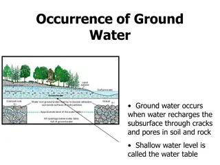
-It is one of the important method that used in shallow investigations. -It is also used in Ground water investigation and all what it related to the aquifer and it depth. -it also useful in quarries. - In engineering projects like finding sink hole or subsidence.
Source of electric currents Natural source (earth magnetic field ) Electromagnetic currents. Man made
Resistivity Resistance R is proportional to length L divided by area A
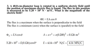
Ohm's law states that the current through a conductor between two points is directly proportional to the voltage across the two points. Introducing the constant of proportionality, the resistance,[1]one arrives at the usual mathematical equation that describes this relationship I= V/R where I is the current through the conductor in units of amperes, V is the voltage measured across the conductor in units of volts, and R is the resistance of the conductor in units of ohms. More specifically, Ohm's law states that the R in this relation is constant, independent of the current. Ohm's law is an empirical relation which accurately describes the conductivity of the vast majority of electrically conductive materials over many orders of magnitude of current. However some materials do not obey Ohm's law, these are called non- ohmic.
Resistivity depend on many factors : 1. mineral grains 2.miosture 3. salinity 4. porosity 5. fracturing
Resistivity in soil depend on many factors 1. type of soil 2. moisture 3. temperature 4. size of grains 5. closeness and packing and pressure 6. chemical composition of salt dissolved the contained water.
Electric conductivity has R (1 / E)
Electrical method has many array: 1. Venner array or Wenner 2. Schlumberger array 3. Polar dipole array
Wenner Array: Electrical Resistivity Methods,
The Wenner electrode array is the simplest of arrays; in it, the four electrodes A, M, N, and B are placed in line and spaced equidistant from each other. The two outer electrodes, A and B, are current electrodes, and the two inner electrodes, M and N, are potential electrodes. With the Wenner array, the resistivity of subsurface layers is found by increasing the distance between the electrodes while maintaining the location of the center point of the array. This method is called vertical electrical sounding (VES) or electrical drilling. Detection of horizontal changes of resistivity is achieved by moving the four electrodes across the surface while maintaining constant electrode separation. This method is called profiling or sometimes electrical trenching. (Source)
Application The Wenner array is commonly used in profiling for lateral exploration of the ground, like soil testing and sometimes VES for vertical exploration of the ground, like defining horizontal layers. The logistic advantage of using the Wenner array when profiling is you only have to move four electrodes for each new measurement along the line.
With the Schlumberger array, for each measurement the current electrodes A and B are moved outward to a greater separation throughout the survey, while the potential electrodes M and N stay in the same position until the observed voltage becomes too small to measure (source). At this point, the potential electrodes M and N are moved outward to a new spacing. As a rule of the thumb, the reasonable distance between M and N should be equal or less than one-fifth of the distance between A and B at the beginning. This ratio goes about up to one-tenth or one- fifteenth depending on the signal strength.
The Schlumberger array is also used for mapping or profiling for lateral resistivity changes. The typical profiling is done by larger fixed AB current electrode pairs and moving MN potential electrode pairs between them. It is also done like Wenner profiling with fixed four ABMN electrode spacing The disadvantage of using profiling, regardless of using the Schlumberger or Wenner arrays, is that it demands homogeneous horizontal layers, which hardly ever occur naturally. The Schlumberger array may also be difficult or confusing for crews to carry out, which may be the reason why the Wenner array has been specified for profiling soil testing according to the ASTM G57 standard.
A pole is a single transmitting electrode, and a dipole is a pair of oppositely charged electrodes that are so close together that the electric field seems to be a single electrode field instead of fields from two different electric poles. The pole-dipole array is similar to the dipole-dipole array, but the pole-dipole array is used when the surveyor needs to see deep within a cross section of the earth. The achievable depth is based entirely on the distance between the two electrodes (the dipole and the pole). The dipole-dipole array, on the other hand, is used to provide a very detailed image of a cross section of the earth but will lose signal if the dipoles are placed too far apart. Like the dipole-dipole array, the pole-dipole array is most often used for mineral and ore exploration.
Resistivity traversing is normally carried out to map horizontal changes in resistivity across a site. Lateral changes in resistivity are detected by using a fixed electrode separation and moving the whole electrode array between each resistivity.
The electrical resistivity method has been used with limited success in the detection of cavities. In view of the time required for a resistivity survey compared with that required for a magnetic survey (discussed above), the resistivity method is not as cost effective in view of the small chances of success. A successful attempt to locate abandoned mineshafts using electrical resistivity is reported by Barker and Worthington (1972). Resistivity techniques have been used successfully in arid and semi-arid areas in groundwater investigations. Some case histories are given by Martinelli (1978). Krynine and Judd (1957) report the use of the electrical resistivity method to locate and assess the nature of faults and fracture zones suspected of running parallel to a proposed tunnel line. Resistivity methods have also been used to locate and map the extent of fissures in karst dolomite for the foundation design of a dolomite processing plant near the town of Matlock