Electric Power System Planning for Industries

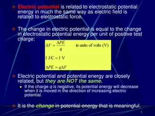
The content discusses the planning of electric power systems for industrial applications, covering aspects such as power demand, power flow, load current, protection on faults, backup power, and more. It delves into topics like power flow analysis, voltage levels, voltage drop, and the relation between voltage, power, and reactive power in the context of industrial electrical systems.

Download Presentation

Please find below an Image/Link to download the presentation.
The content on the website is provided AS IS for your information and personal use only. It may not be sold, licensed, or shared on other websites without obtaining consent from the author.If you encounter any issues during the download, it is possible that the publisher has removed the file from their server.
You are allowed to download the files provided on this website for personal or commercial use, subject to the condition that they are used lawfully. All files are the property of their respective owners.
The content on the website is provided AS IS for your information and personal use only. It may not be sold, licensed, or shared on other websites without obtaining consent from the author.
E N D
Presentation Transcript
Perencanaan Sistem Listrik untuk Industri TEL 12072 Oleh Dr Ir Dina Maizana MT maizanadina@gmail.com
Mari kita berdoa menurut agama dan kepercayaan masing-masing sebelum kelas dimulai. Doa dimulai
Agenda Kebutuhan daya (Power Demand) Aliran daya (Power Flow) Arus beban ( Load Current) Proteksi gangguan (Protection on Fault) Cadangan daya ( Power Unbreakable PS Harmonik Pentanahan Penangkal petir Kapasitor bank Penghematan
Aliran Daya Power Flow is a numerical analysis of the flow of electric power in an interconnected system. A power-flow study usually uses simplified notations such as a one-line diagram and per-unit system, and focuses on various power parameters, such as voltages, voltage angles, real power and reactive power. It analyzes the power systems in normal steady-state operation. aspects of AC Perencanaan Sistem Listrik untuk Industri by DMZ
PSA Relation between Voltage, Power and Reactive Power Perencanaan Sistem Listrik untuk Industri by DMZ
Aliran Daya Perencanaan Sistem Listrik untuk Industri by DMZ
Voltage Drop One of the most important constraints on distribution system design is the voltage level at the customer intake point. This is particularly important for the vast majority of customer taking supplies at low voltage with no means of adjusting the voltage received. A knowledge of the voltage at different locations can indicate the strong and weak parts of a networks. Perencanaan Sistem Listrik untuk Industri by DMZ
Voltage Drop The voltage drop phasor Vdfor a section of line having an impedance Z and carrying current I is given by Vd= IZ In distribution system it is the arithmetic difference between sending and receiving end voltages which is the more useful voltage drop value. A close approximation to this can be obtained from the simplified equivalent Perencanaan Sistem Listrik untuk Industri by DMZ
Voltage Drop The figure has resistance R, reactance X, sending end voltage VSand receiving end voltage Vr. . It carries current I lagging on Vr . During normal load-flow conditions the angle between the receiving and sending end voltage Vrand VS is only a few degrees. For most practical cases the approximation acceptable. is Perencanaan Sistem Listrik untuk Industri by DMZ
Voltage Drop The scalar relationship can be written as = + + V V IR IX cos sin S r The voltage drop Vd in the line is given by = + = + cos sin V V V IR IX I R I X d S r P q IPand Iq represent the resistive and reactive component of load current I Perencanaan Sistem Listrik untuk Industri by DMZ
Voltage Drop In single phase calculations the resistance and reactance of the return path must be included in R and X. For 3-phase systems the line-line voltage drop can be calculated from P + = + ( 3 ) ( tan ) V I R I X R X d P q V Where V is line line voltage and P is the total 3 phase power Perencanaan Sistem Listrik untuk Industri by DMZ
Voltage Drop Example 4.2 Consider the three phases four wire 416 V secondary system with balanced loads at A, B and C as shown in figure below. 0.05 + j0.01 / A 0.1 + j0.02 / B 0.05+j0.05 / C Distribution transformer 30 A Unity p.f. 20 A Cos B = 0.5 lagging 50 A Cos C = 0.9 lagging Determine the following: a) Calculate the total voltage drop using the approximate method b) Calculate the real power per phase for each load c) Calculate the reactive power per phase for each load d) Calculate the kilovolt ampere output and load power factor of the distribution transformer 12
Voltage Drop Solution Using the approximation voltage drop equation Vd = I(R cos + X sin ) a) The voltage drop for each load Vd(A) = 30(0.05x1.0+0.01x0) = 1.5 V Vd(B) = 20(0.15x0.5+0.03x0.866) = 2.02 V Vd(C) = 50(0.2x0.9+0.08x0.436) =1 0.744 V Therefore, the total voltage drop is Vd(Total) = Vd(A)+Vd(B) Vd(C) = 14.264 V 13
Voltage Drop Solution The real power per phase for each load P=VI cos b) the single phase voltage, 416 V = = 240 V V 3 PA=240(30)(1.0)=7.2kW PB=240(20)(0.5)=2.4kW PC=240(50)(0.9)=10.8kW The total real power per phase is: PA+PB+PC=20.4kW The reactive power per phase each load Q=VI sin QA=240(30)(0)=0kvar QB=240(20)(0.866)=4.156kvar QC=240(50)(0.436)=5.232kvar The total reactive power per phase is: QA+QB+QC=9.389kvar c) 14
Voltage Drop Solution The KVA output of the distribution transformer 20 = + = Q P S d) + = 2 2 2 2 49 . . 9 389 22 457 . kVA/phase Total KVA output of the distribution transformer is = S = = 3 3 kVA/phase 457 . 22 67.37 kVA ST The load power factor of the distribution is cos = 20 4 . P = S = 0.908 lagging 22 457 . 15
Power Factor Power factor is the ratio between actual (true) load power (kW) and the apparent load power (kVA) Actual load power(kW) = . . p f Apparent load power (kVA) It is a measure of how effectively the current is being converted into useful work output and more particularly is a good indicator of the effect of the load current on the efficiency of the supply. Perencanaan Sistem Listrik untuk Industri by DMZ
Power Factor Fundamental of Basic Electricity - The Power Triangle P - kW Q - kVar S - kVA = + 2 2 S P Q kW = Power Factor kVA Perencanaan Sistem Listrik untuk Industri by DMZ
Power Factor Equipment Causing Poor Power Factor Lightly loaded induction motor. Examples of this type of equipment and their approximate power factor are: 70% power factor or better: Air conditioners, pumps, center less grinders, cold header, up setter, fans or blower 60% to 70% power factor: Induction furnaces, standard stamping machines and weaving machines 60% power factor and below: Single-stroke presses, automated machine tools, finish grinders, welders Perencanaan Sistem Listrik untuk Industri by DMZ
Power Factor Reactive Power Problem (Motor) Example that a motor is rated at 10,000W at 0.8 power factor. The resistance is 5ohm. At 415V, the motor will require the following amount of current: I=10000/( 3x0.8x415)=17.39A Losses when pf =0.8 : I2R=(17.39)2(5)=1,512W The same motor rated at 0.65 power factor will require: I=10000/( 3x0.65x415)=21.403A Losses when pf=0.65 : I2R=(21.403)2(5)=2290.4W Low Power Factor = Higher Losses Perencanaan Sistem Listrik untuk Industri by DMZ
Power Factor Minimum Power Factor Customers are advise to maintain power factor at minimum of 0.85 Perencanaan Sistem Listrik untuk Industri by DMZ
Power Factor How to Improve Power Factor Customers are advised to follow these steps:- Install capacitors (KVAR Generators) Capacitor Corrector Synchronous generators Synchronous motors Minimise operations of idling or lightly loaded motors. Avoid operating equipment above its rated voltage. Replace standard motors as they burn out with energy efficient motors. Perencanaan Sistem Listrik untuk Industri by DMZ
Power Factor Power Factor Improvement Example Of Power Flow Diagram Of Industrial Plant Perencanaan Sistem Listrik untuk Industri by DMZ
Power Factor Benefits of Improving Power Factor Benefit 1: Reducing KW billing demand Low Power Factor requires high reactive power (KVAR) and apparent power (KVA), which is the power that electric utilities supplies. Therefore, a facility s low power factor forces electric utilities to increase its generation and transmission capacity in order to handle this extra demand. By increasing power factor, customers use less KVAR. This results in less KW, which equates to cost savings for electric utilities . Benefit 2: Eliminating power factor surcharge Utility companies all around the world charge customers an additional surcharge when their power factor is less than 0.95. In fact, some utilities are not obliged to deliver electricity to their customers at any time the customer s power factor falls below 0.85.
Power Factor Thus, customer can avoid this additional surcharge by increasing power factor. Benefit 3: Increased system capacity and reduced system losses in electrical system Low power factor causes power system losses in the customer s electrical system. By improving power factor, these losses can be reduced. With the current rise in the cost of energy, increased facility efficiency is important. Moreover, with lower system losses, customers are able to add additional load in their electrical system.
Power Factor Benefit 4: Increased voltage level in electrical system, resulting in more efficient motors As mentioned before, low power factor causes power system losses in customer s electrical system. As power losses increase, customer may experience a voltage drop. Excessive voltage drops can cause overheating and premature failure of motors and other inductive equipment. Therefore, by raising the power factor, customers can minimize these voltage drops along feeder cables and avoid related problems. Motors will run more efficiently, with a slight increase in capacity and starting torque.
Aliran Daya Pada suatu industri yang menggunakan Listrik dari PLN untuk kebutuhan berbagai peralatan listriknya, adapun listrik yang digunakan adalah listrik 3 fasa dengan tegangan 380V/220V, dengan rincian kebutuhan daya berbagai peralatan listrik yang digunakan sebagai berikut: Perencanaan Sistem Listrik untuk Industri by DMZ
Aliran Daya 1 unit Elektro motor 3 fasa 380 V daya 75 kW 1 unit Elektro motor 3 fasa 380 V daya 30 kW 1 unit Elektro motor 3 fasa 380 V daya 15 kW 1 unit Elektro motor 3 fasa 380 V daya 7,5 kW 1 unit Heater 3 fasa 380 V daya 22 kW 1 unit blower 3 fasa 380 V 18 kW 30 buah lampu mercury 250 W (10 buah/fasa) total (30 x250) / 3 = 2,5kW Perencanaan Sistem Listrik untuk Industri by DMZ
Aliran Daya 380V/220V 0.05 + j0.01 / 3 ph, 380 V, 75 kW, R = 2 0.05 + j0.01 / 3 ph, 380 V, 30 kW, R = 2 0.05 + j0.01 / 3 ph, 380 V, 15 kW, R = 2 0.05 + j0.01 / 3 ph, 380 V, 7,5 kW, R = 2 0.05 + j0.01 / 3 ph, 380 V, 22 kW, R = 5 3 ph, 380 V, 18 kW, R = 2 0.05 + j0.01 / 30 buah lampu mercury 250 W (10 buah/fasa) total (10 x250) / 3 = 2,5kW, R = 1 0.05 + j0.01 / Perencanaan Sistem Listrik untuk Industri by DMZ
Aliran Daya Determine the following: a) If each load have pf = 0.85, 1) Calculate the total voltage drop using the approximate method 2) Calculate the reactive power per phase for each load 3) Calculate the kilovolt ampere output and load power factor of the distribution transformer 4) Calculate losses for each load 5) Calculate total losses that produce by load. Perencanaan Sistem Listrik untuk Industri by DMZ
Aliran Daya R = 0.05 ; X = j0.01 / a) Calculate the total voltage drop using the approximate method 1 unit Elektro motor 3 fasa 380 V daya 15 kW 15 ? ? 380 ? ??= 1,393? 1 unit Elektro motor 3 fasa 380 V daya 7,5 kW 0.05 + 0.01?tan65 = P 3 + = + ( 3 ) ( tan ) V I R I X R X d P q V LL 1 unit Elektro motor 3 fasa 380 V daya 75 kW, Pf =0,85; = cos-1 (0,85)= 65o 7,5 ? ? 380 ? ??= 0,6967? 0.05 + 0.01?tan65 = 75 ? ? 380 ? ??= 6,967? 1 unit Elektro motor 3 fasa 380 V daya 30 kW 0.05 + 0.01?tan65 = 30 ? ? 380 ? ??= 2,787? 0.05 + 0.01?tan65 = Perencanaan Sistem Listrik untuk Industri by DMZ
Aliran Daya 1 unit Heater 3 fasa 380 V daya 22 kW 30 buah lampu mercury 250 W (10 buah/fasa) total (30 x250) / 3 = 2,5kW 22 ? ? 380 ? ??= 2,084? 1 unit blower 3 fasa 380 V 18 kW 0.05 + 0.01? tan65 = 2,5 ? ? 380 ? ??= 0.01? tan0 = 0,3289? Total drop tegangan = 15,9 V 0.05 + 18 ? ? 380 ? ??= 0.01? tan65 1,672? 0.05 + Perencanaan Sistem Listrik untuk Industri by DMZ
Aliran Daya P=VI cos ; I = P/V cos Q=VI sin = V(P/V cos ) sin = P tan 1 unit Elektro motor 3 fasa 380 V daya 75 kW, Pf =0,85; = cos-1 (0,85)= 65o Q = 75 kW tan 65o = 110 kVAr 1 unit Elektro motor 3 fasa 380 V daya 30 kW, Q = 30 kW tan 65o = 64,34 kVAr 1 unit Elektro motor 3 fasa 380 V daya 15 kW, Q = 15 kW tan 65o = 32,17 kVAr 1 unit Elektro motor 3 fasa 380 V daya 7,5 kW, Q = 7,5 kW tan 65o = 16,08 kVAr 1 unit Heater 3 fasa 380 V daya 22 kW Q = 22 kW tan 65o = 47,18 kVAr 1 unit blower 3 fasa 380 V 18 kW Q = 18 kW tan 65o = 38,6kVAr 30 buah lampu mercury 250 W (10 buah/fasa) total (30 x250) / 3 = 2,5kW Q = 2,5 kW tan 65o = 5,36 kVAr Total daya reaktif = 313,73 kVAr Perencanaan Sistem Listrik untuk Industri by DMZ
Aliran Daya Calculate the kilovolt ampere output and load power factor of the distribution transformer ? = 356,83 ?? ?2+ ?2= 1702+ 313,732= ? ?= 170 356,83= 0,476 or 47,6% ?? = Perencanaan Sistem Listrik untuk Industri by DMZ
Aliran Daya Calculate losses for each load ? 3 ??? ?? ? = Losses = I2R 1 unit Elektro motor 3 fasa 380 V daya 75 kW, Pf =0,85; = cos-1 (0,85)= 65o 75000 3 380 0.85= 134 A; losses = 1342 x 2 = 35,912kW 1 unit Elektro motor 3 fasa 380 V daya 30 kW, Pf =0,85; = cos-1 ? = 3 380 0.85= 45,442 A; losses = 45,4422 x 2 = kW 1 unit Elektro motor 3 fasa 380 V daya 15 kW, Pf =0,85; = cos-1 Q = 15 kW tan 65o = 32,17 kVAr 1 unit Elektro motor 3 fasa 380 V daya 7,5 kW, Pf =0,85; = cos-1 Q = 7,5 kW tan 65o = 16,08 kVAr ? = 30000 Perencanaan Sistem Listrik untuk Industri by DMZ
. THANK YOU FOR COMING
TUGAS 1.2 Introduction to Power Electronic by DMZ