Electrical Engineering Concepts and Laws Overview
Explore the fundamental concepts and laws in electrical engineering, including units of measurement, electric current, voltage, resistance, and electrical power. Learn about the International System of Units, the flow of electrical charges, and the effect of temperature on electrical resistance. Gain insights into basic definitions and essential principles in electrical engineering.

Download Presentation

Please find below an Image/Link to download the presentation.
The content on the website is provided AS IS for your information and personal use only. It may not be sold, licensed, or shared on other websites without obtaining consent from the author. If you encounter any issues during the download, it is possible that the publisher has removed the file from their server.
You are allowed to download the files provided on this website for personal or commercial use, subject to the condition that they are used lawfully. All files are the property of their respective owners.
The content on the website is provided AS IS for your information and personal use only. It may not be sold, licensed, or shared on other websites without obtaining consent from the author.
E N D
Presentation Transcript
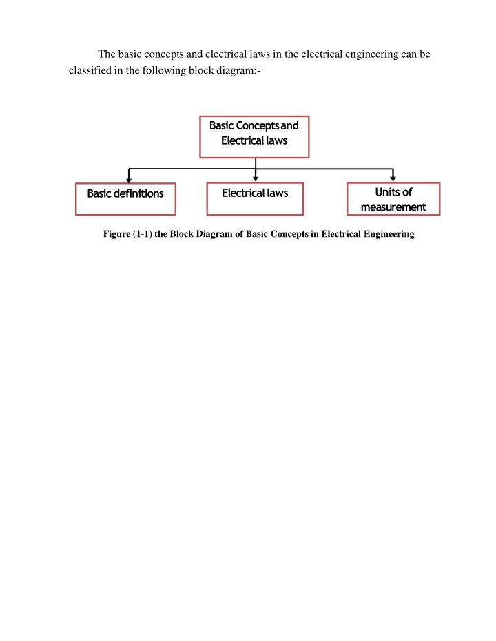
The basic concepts and electrical laws in the electrical engineering can be classified in the following block diagram:- Basic Conceptsand Electricallaws Units of measurement Electricallaws Basicdefinitions Figure (1-1) the Block Diagram of Basic Concepts in Electrical Engineering
The International System of Units (SI) The base units of the (SI) are listed as shown in table (1), while some SI Derived Units are listed in table (2). Table (1) SI Base Units Name of Unit meter kilogram second ampere kelvin mole candela Quantity Length Mass Time Electric current Thermodynamic temperature Amount of substance Luminous intensity Symbol m kg s A K mol cd 2
The Electric current Fig (1-2) the Flow of Electrical Charges Through Conductor Hence:- i=dq (1.1) dt Where: i = the electric current (A), q= the electric charge (C) and t= the time (s). Fig (1-3) the Waveforms of Direct and Alternating Current
2- The voltage (V) is defined as the amount of energy (w, joules) to be given to a unit of charge to flow through a conductor.it describes the potential for charge to do work. Hence:- W V =Q (C) (1.3) (J) (V) Figure (1-5) voltmeter. b-A 12v Battery Connected with Electrical Load. c- Measurement of the Electrical Current in lab using ammeter. a- Measurement the Voltage of A 12v Battery using
The Resistance and Electrical Power Resistance defined as the property of substance due to which it opposes the flow of electric current through it. In many circumstances, R= l/A ------------ (1.4) The symbol of resistance is (R) and its unit is ( or Ohm), from equation (1.4) l A the wire cross-sectional area in (m ). the resistivity of the material in ( -m) . the wire length in (meters (m)) . 6
Also Electrical resistance of wire depends on temperature, as temperature increases, the resistance increases and the effect of temperature on the resistance of conductor (cooper) can be shown in the figure (1-6). Figure (1-6) the Effect of Temperature on the Resistance of Cooper Wire
And the following equations may be used as the method of determining the resistance at any temperature:- T +T1 = T+T2 ------(1.5) R1 R2 For anyconductor -234.5 +T1 = -234.5+T2 R1 R2 For cooperconductor And if we have a temperature coefficient ( ) then the following equation is applied R2 =R1(1+ (T2 T1)) (1.6) 8
Power (P):- its a rate of doing work to convert energy from one form to another in a specified amount of time. Hence:- Power(watt) =work done(Joule)=w(J) time(second) P(W)=W(J) (1.7) t(s) t(s) {Note that 1hp=746W}
Where Energy can be thought of as the ability to do work and it can be determined as:- Energy = power (W) time (h) in (watt- hour) w= P (W) t (h) While Energy in (kWh) is w= [power (W) time (h)] /1000 01
Electrical Circuit It is the mathematical model that approximates the behavior of the actual electrical system. The electrical circuit usually contains a battery or other electromotive force to create the current and without the source of energy to drive the circuit no current will flow.
Series Combination Series electrical circuits consist of any number of elements joined at terminal providing at least one closed path through which electric current can flow. Figure (2-1) shows a sample of series electrical circuit Figure (2-1) Series Electrical Circuit RT = R1+ R2+ R3+R4 IT = I1= I2= I3=I4 --------------(2-1) --------------(2-2) And IT RT = I1R1+ I2R2+ I3R3+ I4R4 E = V1+ V2 + V3+ V4 --------------(2-3) 02
Parallel Combination Any two elements, branches, or network are in parallel if they have two points connected in common as shown in figure (2-3). Figure (2-3) Parallel Combination For the parallel circuit shown in figure (2-4), we can find the following:- 1=1+1+1 (2 4) RT R1 R2 R3 E =V1 =V2=V3 (2 5) IT=I1+I2+I3 (2 6)
Kirchhoff Current Law (KCL) States that at every instant of time the sum of the electric currents that flowing into any node of a circuit must be equal thesum of the electric currents leaving the node. Therefore the algebraic sum of all currents entering and exiting a node must equal zero". I = 0 (KCL) Or 04
2.5.2 Kirchhoff Voltage Law (KVL) States that the algebraic sum of the voltages or potentials which rise or drop around closed path or loop is equal to zero. V = 0 (KVL) For the electric circuit shown in figure (2-8) + E - V1- V2 -V3 - V4 = 0 E =V1+ V2 +V3 + V4 Vrises = Vdrops Fig(2-8) the Voltage and Current Divider rules the Voltage Divider Rule It is a method to find the voltage across the resistor in series combination such as branch, loop or circuit and the rule is R R V = n V T n T Where Vn= the voltage across the resistance. VT= the total voltage applied to the series combination. Rn= the resistance in which the voltage across it is required. RT= the total series resistance of the series combination.
06 The Current Divider Rule This rule is applied in parallel combination of resistance circuitor branches and it is I =I RT written as: n T n R Where In= the current through the resistance. IT= the total current enter the parallel combination. Rn= the resistance in which the current is required. RT= the total parallel resistance of the parallel combination. 06
Star Delta and Delta Star Conversions Thesemethodsofconversionsmay beusedforsolving complicatednetworks having number of branches. i. Star(Y or T) ConnectionDyagram In this method of connection the three ends of electrical element (resistor) are joined together at point N as shown in figure (4-1) Figure (4-1) the Connection Diagram of Star. 2
ii. Delta ( or )Connection In this type of connection the electrical element (resistor) are joined as shown in figure (4-2) Figure (4-2) the Schematic Diagram of Delta Connections.
Star to Delta Conversion If we have three resistances (R1, R2and R3) connected in star shape as in figure (4-3), Then the conversion to delta shape can be easily done by using the following equations:- 1 2 RR +RR +RR R = 1 3 R 2 3 A 3 1 3 RR +RR +RR R = 1 2 R 3 2 B 2 R R +R R +RR R = 2 3 2 1 R 3 1 C 1 Figure (4-3) Star to Delta Conversion. 4
Delta StarConversions If we have three resistances (RA, RBand RC) connected in delta shape as in figure (4-5), Then the conversion to star shape can be easily done by using the following equations:- RARB R =R + R + R 1 A B C RARC R =R + R + R 2 A B C RCRB R =R + R + R 3 A B C Figure (4-5) the Delta to Star Conversion.
The Superposition Theorem State that: - In any linear circuit containing multiple independent sources, the current through an element in this circuit (or voltage across) is the algebraic sum of the currents through (or voltages across) that element due to each independent source actingalone. I1=( I11)+( I12)+( I13)+ +( I1n) Where n = number of sources 6
Steps of Applying Superposition Principle:- 1 Deactivate all independent sources except one source. If the internal resistance of the sources is neglected then the voltage source is replaced with a Short Circuit (R= 0 ) and the current source is replaced with an open circuit (R = ) respectively then find the corresponding (V or I) due to that active source. 2 Repeat step (1) for each of the other independent sources. 3 Find the total contribution (V or I) by adding algebraically all the currents or voltages due to the independent sources.
Thevenin's Theorem Thevenin's Theorem states that: - it is possible to simplify a complex linear circuit to an equivalent circuit consists of single voltage source and series resistance connected to a load. The Thevenin s equivalent circuit is shown in figure (4-7), Figure (4-7) the Thevenin s equivalent circuit. 8
Steps of Applying Thevenin's Theorem:- 1- Remove the load from the original circuit. 2- Mark the remaining two terminals (a,b). 3- Find RThevenin or (RTh) with replacing all sources in the circuit with the corresponding equivalent circuit, then find the resultant resistance. 4 FindETheveninor(ETh)byfirstreturning all thesources to theoriginalposition,then find the open circuit voltage between the two terminals a, b. 5 Draw Thevenin s equivalent circuit as shown in figure (4-7).
Nortons Theorem State that: - Any two-terminal linear bilateral dc network can be replaced by an equivalent circuit consisting of a current source and a parallel resistor, as shown in Figure (4-8) Figure (4-8) Norton s Equivalent Circuit 01
The DC machine can be subdivided into DC generators and DC motors, which they have the same general construction. Motor is a device which converts Electrical power into Mechanical power while generator is a device which converts Mechanical power into Electrical power. In fact, when the machine is being assembled, the workmen usually do not know whether it is a DC generator or motor. Any dc generator can be run as a dc motor and vice-versa.
Note that all DC machines have five principal components (i) Fieldsystem. The function of the field system is to produce uniform magnetic field within which the armature rotates. (ii) Armature core. The armature core is formed as a cylindrical core and rotates between the field poles. (iii) Armature winding. It is an insulated conductor that is connected in a suitable manner in the slots of the armature core. 02
(iv) Commutator. It is a mechanical rectifier which converts the alternating voltage generated in the armature winding into direct voltage across the brushes. (v) Brushes. Thepurposeofbrushesinadcgeneratoristoensureelectricalconnections between the rotating commutator and stationary external load circuit. DC motors are of two types: one is brushed dc motor and the other one is brushless dc motor.
The diagram given below represents the various parts of a DC machine. 04
The unit of rated power of the generator is (kVA) = Voltage Current The unit of rated power of the generator is (kW) = Voltage Current (Power Factor)
Some Types of DC Motors A direct-current machine is a machine consisting of a rotating armature winding connected to a commutator and stationary magnetic poles which are excited from a direct current source or permanent magnets. Direct-current motors are of four general types: 1 shunt-wound 2 series-wound 3 compound-wound 4 Permanent-magnet. 06
1- DC Shunt Motor A shunt wound DC motor has the armature and field (stator) coils connected in parallel (or shunt) across the power source as shown in figures
Series-wound motor. Aseries-wound motoris a dc motor in which the field winding is connectedin series with the armature circuit. 08
Compound-woundmotor. A compound-wound motor is a dc motor with two separate field windings: one connected as in a straight-shunt wound motor, and the other in series with the armature circuit. Compound-wound motors are produced by including both series and shunt fields.
Permanent magnet motor. A permanent magnet motor is a dc motor in which the field excitation is suppliedby permanent magnets. Steps of Applying Norton's Theorem:- 1.Remove that portion of the network across which the Norton equivalent circuit is found. 2. Mark the terminals of the remaining two-terminal network. 3.Calculate RN by first setting all sources to zero (voltage sources are replaced with short circuits and current sources with open circuits) and then finding the resultant resistance between the two marked terminals. (If the internal resistance of the voltage and/or current sources is included in the original network, it must remain when the sources are set to zero.) 4.CalculateINbyfirstreturningallsourcestotheiroriginalpositionandthenfinding the short-circuit current between the marked terminals. It is the same current that would be measured by an ammeter placed between the marked terminals. 5.Draw the Norton equivalent circuit with the portion of the circuit previously removed replaced between the terminals of the equivalent circuit. 21

")


 is defined as the amount of energy (w,")


:- it’s a rate of doing work to convert energy")


")
")


Connection")


")