Electrical Engineering Fundamentals: Course Details and Syllabus
Explore the fundamentals of Electrical Engineering through topics such as conservation of power, electrical circuits analysis, and fundamental principles. Dive into key concepts like Ohm's Law, Thevenin Theorem, and more in this comprehensive course.

Download Presentation

Please find below an Image/Link to download the presentation.
The content on the website is provided AS IS for your information and personal use only. It may not be sold, licensed, or shared on other websites without obtaining consent from the author. If you encounter any issues during the download, it is possible that the publisher has removed the file from their server.
You are allowed to download the files provided on this website for personal or commercial use, subject to the condition that they are used lawfully. All files are the property of their respective owners.
The content on the website is provided AS IS for your information and personal use only. It may not be sold, licensed, or shared on other websites without obtaining consent from the author.
E N D
Presentation Transcript
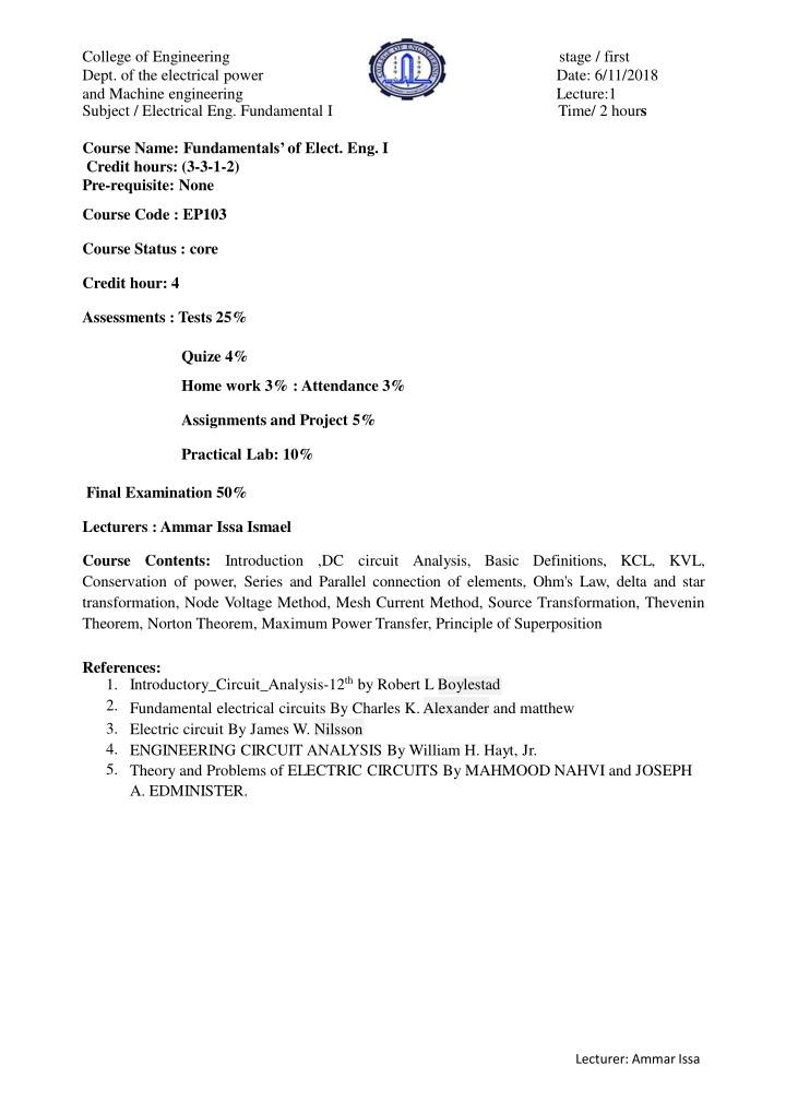
College of Engineering Dept. of the electrical power and Machine engineering Subject / Electrical Eng. Fundamental I stage / first Date: 6/11/2018 Lecture:1 Time/ 2 hours Course Name: Fundamentals of Elect. Eng. I Credit hours: (3-3-1-2) Pre-requisite: None Course Code : EP103 Course Status : core Credit hour: 4 Assessments : Tests 25% Quize 4% Home work 3% :Attendance 3% Assignments and Project 5% Practical Lab: 10% Final Examination 50% Lecturers :Ammar Issa Ismael Course Contents: Conservation of power, Series and Parallel connection of elements, Ohm's Law, delta and star transformation, Node Voltage Method, Mesh Current Method, Source Transformation, Thevenin Theorem, Norton Theorem, Maximum Power Transfer, Principle of Superposition Introduction ,DC circuit Analysis, Basic Definitions, KCL, KVL, References: 1. Introductory_Circuit_Analysis-12th by Robert L Boylestad 2. 3. 4. 5. Theory and Problems of ELECTRIC CIRCUITS By MAHMOOD NAHVI and JOSEPH A. EDMINISTER. Fundamental electrical circuits By Charles K. Alexander and matthew Electric circuit By James W. Nilsson ENGINEERING CIRCUIT ANALYSIS By William H. Hayt, Jr. Lecturer: Ammar Issa
College of Engineering Dept. of the electrical power and Machine engineering Subject / Electrical Eng. Fundamental I SYSTEMS OF UNITS stage / first Date: 6/11/2018 Lecture:1 Time/ 2 hours ATOMS AND THEIR STRUCTURE The orbiting electron carries a negative charge equal in magnitude to the positive charge of the proton The atomic structure of any stable atom has an equal number of electrons and protons. Lecturer: Ammar Issa
College of Engineering Dept. of the electrical power and Machine engineering Subject / Electrical Eng. Fundamental I stage / first Date: 6/11/2018 Lecture:1 Time/ 2 hours Coulomb s law is the force of attraction between the nucleus and the electron of atomic. where F is in Newton's (N), k = a constant = 9.0 109 Nm2/C2, Q1 and Q2 are the charges in coulombs and r is the distance between the two charges in meters. Other metals, that exhibit the same properties as copper, but to a different degree, are silver, gold, and aluminum, and some rarer metals such as tungsten. Additional comments on the characteristics of conductorsare in thefollowingsections. Lecturer: Ammar Issa
College of Engineering Dept. of the electrical power and Machine engineering Subject / Electrical Eng. Fundamental I VOLTAGE stage / first Date: 6/11/2018 Lecture:1 Time/ 2 hours every source of voltage is established by simply creating a separation of positive and negative charges. One coulombof chargeis the total chargeassociatedwith6.242 *1018electrons. if a total of 1 joule (J) of energy is used to move the negative charge of 1 coulomb (C), there is a differenceof 1 volt (V) betweenthe two points. Lecturer: Ammar Issa
College of Engineering Dept. of the electrical power and Machine engineering Subject / Electrical Eng. Fundamental I CURRENT; theappliedvoltageis the startingmechanism thecurrentis a reactionto the appliedvoltage stage / first Date: 6/11/2018 Lecture:1 Time/ 2 hours The instant the final connection is made, the free electrons of negative charge drift toward the positive terminal, while the positive ions left behind in the copper wire simply oscillate in a mean fixed position. The flow of charge (the electrons) through the bulb heats up the filament of the bulb through friction to the point that it glows red-hot and emits the desired light. if 6.242 *1018electrons (1 coulomb) pass through the imaginary plane in Fig. 9 in 1 second, the flow of charge, or current, is said to be 1 ampere (A). Lecturer: Ammar Issa
College of Engineering Dept. of the electrical power and Machine engineering Subject / Electrical Eng. Fundamental I stage / first Date: 6/11/2018 Lecture:1 Time/ 2 hours Using the coulomb as the unit of charge, we can determine the current in amperes from the following equation The applied voltage (or potential difference) in an electrical/electronic system is the pressure to set the system in motion, and the current is the reaction to that pressure. VOLTAGE SOURCES An electromotive force (emf) is a force that establishes the flow of charge (or current) in a system due to the application of a difference in potential. In general, dc voltage sources can be divided into three basic types: (1)batteries (chemical action or solar energy), (2) Generators (electromechanical), (3)Power supplies (rectification a conversion process to be described in your electronics courses). CONDUCTORS AND INSULATORS Conductors are those materialsthat permit a generous flow of electrons with very little external force (voltage) applied. In addition, good conductors typically have only one electron in the valence (most distant from the nucleus) ring. Insulators are those materialsthat have very few free electrons and require a large applied potential (voltage) to establish a measurable current level. Lecturer: Ammar Issa
College of Engineering Dept. of the electrical power and Machine engineering Subject / Electrical Eng. Fundamental I stage / first Date: 6/11/2018 Lecture:1 Time/ 2 hours RESISTANCE: CIRCULARWIRES The resistanceof any materialis due primarilyto fourfactors: 1. Material(resistivity) 2. Length 3. Cross-sectionalarea 4. Temperatureof the material Lecturer: Ammar Issa
College of Engineering Dept. of the electrical power and Machine engineering Subject / Electrical Eng. Fundamental I stage / first Date: 6/11/2018 Lecture:1 Time/ 2 hours Lecturer: Ammar Issa
College of Engineering Dept. of the electrical power and Machine engineering Subject / Electrical Eng. Fundamental I stage / first Date: 6/11/2018 Lecture:1 Time/ 2 hours WIRE TABLES : The wire table was designed primarily to standardize the size of wire produced by manufacturers. As a result, the manufacturer has a larger market, and the consumer knows that standard wire sizes will always be available. The table was designed to assist the user in every way possible; it usually includes data such as the cross-sectional area in circular mils, diameter in mils, ohms per 1000 feet at 20 C, and weight per 1000 feet. The American Wire Gage (AWG) sizes are given in Table 2 for solid, round copper wire. A column indicating the maximum allowable current in amperes, as determined by the National Fire Protection Association, has also been included. The chosen sizes have an interesting relationship. Lecturer: Ammar Issa
College of Engineering Dept. of the electrical power and Machine engineering Subject / Electrical Eng. Fundamental I stage / first Date: 6/11/2018 Lecture:1 Time/ 2 hours Lecturer: Ammar Issa