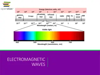
Electromagnetic Principles in Electrical Engineering
In Electrical Engineering, understanding electromagnetic principles is crucial. Explore concepts like Fleming's Left Hand Rule, Fleming's Right Hand Rule, Lenz's Law, and the working principle of a DC Generator. Dive into the construction and operation of DC machines through detailed images. Discover the intricate workings behind converting mechanical energy to electrical energy and the essential components required. Gain insights into determining the direction of forces, induced EMF, and more with practical examples and illustrations.

Download Presentation

Please find below an Image/Link to download the presentation.
The content on the website is provided AS IS for your information and personal use only. It may not be sold, licensed, or shared on other websites without obtaining consent from the author.If you encounter any issues during the download, it is possible that the publisher has removed the file from their server.
You are allowed to download the files provided on this website for personal or commercial use, subject to the condition that they are used lawfully. All files are the property of their respective owners.
The content on the website is provided AS IS for your information and personal use only. It may not be sold, licensed, or shared on other websites without obtaining consent from the author.
E N D
Presentation Transcript
Flemings left hand rule Used todeterminethedirectionof forceacting on a current carrying conductorplaced in a magneticfield . The middlefinger, theforefingerand thumbof the lefthandare keptatrightanglestoone another. The middlefinger represent thedirection of current The fore finger representthedirectionof magneticfield Thethumbwill indicatethedirectionof forceactingon theconductor. Thisruleisused in motors.
Flemings Right hand rule Used todeterminethedirectionof emf induced inaconductor Themiddlefinger, theforefingerand thumbof the left hand are kept at right angles to one another. Theforefingerrepresentthedirection of magneticfield Thethumbrepresentthedirectionof motionof theconductor Themiddlefingerwill indicatethe directionof theinductedemf . This rule is used in DC Generators
LensLaw Thedirectionof inducedemf isgivenby Lenz slaw. According tothislaw,theinducedemf will be acting in such a way so as to oppose the verycauseof productionof it. e = -N (d /dt) volts
DC Generator Mechanical energyisconverted to electric energy Three requirements are essential 1. Conductors 2. Magneticfield 3. Mechanicalenergy
Working principle Ageneratorworksontheprinciplesof Faraday s lawof electromagneticinduction Whenever a conductor is moved in the magneticfield ,an emf is inducedand the magnitudeof the induced emf is directly proportional to the rate of change of flux linkage. Thisemf causesacurrentflow if the conductorcircuitisclosed .
Construction of DC Generator Field system Armaturecore Armature winding Commutator Brushes
Armature winding There are 2 types of winding Lap and Wave winding Lapwinding A = P Wave winding A = 2 It is used in low current output and highvoltage. The armature windings are divided into no. of sections equal totheno of poles 2 brushes
Field system Itisforuniform magneticfield within whichthearmaturerotates. Electromagnets are preferred in comparisonwithpermanent magnets They are cheap , smaller in size , producegreatermagneticeffectand Field strengthcan bevaried
Field system consists of the following parts Yoke Pole cores Pole shoes Fieldcoils
Armature core Thearmaturecoreiscylindrical Highpermeabilitysiliconsteel stampings Impregnated Lamination istoreducetheeddy currentloss
Commutator Connectwithexternal circuit Convertsacintounidirectional current Cylindrical inshape Made of wedge shaped copper segments Segments are insulated from each other Eachcommutatorsegmentisconnected to armatureconductors bymeansof acustripcalled riser. Noof segmentsequal tonoof coils
Carbonbrush Carbon brushesareused in DC machines becausetheyaresoftmaterials Itdoes notgeneratespikeswhen theycontact commutator Todeliverthecurrentthroarmature Carbon isused forbrushes because ithas negativetemperaturecoefficientof resistance Self lubricating , takesitsshape, improving areaof contact
Carbon brush Brush leads (pig tails) Brushrocker( brushgear) Frontendcover Rearendcover Cooling fan Bearing Terminal box
EMF equation Let, = flux perpoleinweber Z =Total numberof conductor P = Numberof poles A = Numberof parallel paths N =armaturespeed inrpm Eg =emf generated inanyonof the parallel path
EMF equation Flux cut by 1 conductor in 1 revolution Flux cut by 1 conductor in 60 sec Avg emf generated in 1 conductor Number of conductors in each parallel path = P * = P N /60 =P N/60 = Z /A Eg = P NZ/60A
DC generators are generally classified according to their method of excitation . Separately excited DC generator Self excited D C generator
Series wound generator Shunt wound generator Compound wound generator Short shunt & Long shunt Cumulatively compound & Differentially compound
No load saturation characteristic (Eo/If) Internal or Total characteristic (E/ Ia) External characteristic (V/I)
Critical field resistance For appreciable generationof emf, the field resistance must be always less certain resistance, that resistance is called as the critical resistance of the machine.
Magnetic neutral axis : It is perpendicular to the lines of force between the two opposite adjacent poles. Leading pole Tip (LPT) : It is the end of the pole which first comes in contact with the armature. Trailing pole tip : It is the end of the pole which comes in contact later with the armature.
Interaction of Main field flux with Armature field flux
It decreases the efficiency of the machine It produces sparking at the brushes It produces a demagnetising effect on the main poles It reduces the emf induced Self excited generators some times fail to build up emf
1.Brushes must be shifted to the new position of the MNA 2.Extra turns in the field winding 3.Slots are made on the tips to increase the reluctance 4. The laminated cores of the shoe are staggered 5.In big machines the compensating winding at pole shoes produces a flux which just opposes the armature mmf flux automatically.
The change in direction of current takes place when the conductors are along the brush axis . During this reverse process brushes short circuit that coil and undergone commutation Due to this sparking is produced and the brushes will be damaged and also causes voltage dropping.
Losses in DC Generators 1. Copper losses or variable losses 2. Stray losses or constant losses Stray losses : consist of (a) iron losses or core losses and (b) windage and friction losses . Iron losses : occurs in the core of the machine due to change of magnetic flux in the core . Consist of hysteresis loss and eddy current loss. Hysteresis loss dependsupon the frequency, Flux density , volume and type of the core .
Hysteresis loss dependsupon the frequency , Flux density , volume and type of the core . Eddy current losses : directly proportional to the flux density, frequency, thickness of the lamination . Windage and friction losses are constant due to the opposition of wind and friction .
Applications Shunt Generators: a. in electro plating b. for battery recharging c. as exciters for AC generators. Series Generators: A. As boosters B. As lighting arc lamps
Converts Electrical energy into Mechanical energy Construction : Same for Generator and motor Working principle : Whenever a current carrying conductor is placed in the magnetic field , a force is set up on the conductor.
The induced emf in the rotating armature conductors always acts in the opposite direction of the supply voltage . According to the Lenz s law, the direction of the induced emf is always so as to oppose the cause producing it . In a DC motor , the supply voltage is the cause and hence this induced emf opposes the supply voltage.
DC motorsaremainlyclassified into threetypesas listed below: Shuntmotor Seriesmotor Compound motor Differentialcompound Cumulativecompound
Theturning ortwisting forceaboutan axis iscalled torque. P = T * 2 N/ 60 EbIa= Ta* 2 N/ 60 T I a Ta I2a
Characteristic of DC motors T/ Ia characteristic N/ I a characteristic N/T characteristic
Speed control of DC motors According tothespeedequationof adc motor N Eb/ V- IaRa/ Thusspeedcan becontrolled by- Flux control method: By Changing the flux by controlling thecurrentthroughthefieldwinding. Armature control method: By Changing the armature resistancewhichinturnchangesthevoltageapplied acrossthearmature
Flux control Advantagesof fluxcontrol: Itprovidesrelativelysmoothand easycontrol Speedcontrolaboverated speed ispossible Asthefieldwindingresistanceis highthefieldcurrent is small. Power loss in the external resistance is small . Hencethis method iseconomical Disadvantages: Fluxcan beincreasedonlyuptoitsratedvalue Highspeedaffectsthecommutation, motoroperation becomesunstable
Armature voltage control method The speed is directly proportional to the voltage applied acrossthearmature . Voltage across armature can be controlled by adding a variable resistance in series with the armature Potential dividercontrol : If the speed control from zero to the rated speed is required , by rheostatic method then the voltage across the armature can be varied by connecting rheostatinapotential dividerarrangement .
Needed tolimitthestartingcurrent. 1. Twopointstarter 2. Threepointstarter 3. Fourpointstarter
Testing of DC machines Todeterminetheefficiencyof as DC motor, theoutput and inputshould beknown. Therearetwomethods. Theload testorThedirectmethod Theindirectmethod Direct method: In this method , the efficiency is determined by knowing theinputandoutputpowerof themotor. Indirectmethod: Swinburne stestisan indirectmethod of testing DC shunt machines to predetermine the effficency,asa motorand asa Generator. In this method, efficiency is calculated by determining the losses .
Shunt Motor: Blowers and fans Centrifugal and reciprocating pumps Lathe machines Machine tools Milling machines Drilling machines
Series Motor: Cranes Hoists , Elevators Trolleys Conveyors Electric locomotives