Electromagnetic Waves and Antennas: Basics and Application
Dive into the fundamentals of electromagnetic waves, exploring their properties, generation spectrum, and applications. Learn about radio frequencies, propagation, and antenna theory for effective communication engineering.

Download Presentation

Please find below an Image/Link to download the presentation.
The content on the website is provided AS IS for your information and personal use only. It may not be sold, licensed, or shared on other websites without obtaining consent from the author. If you encounter any issues during the download, it is possible that the publisher has removed the file from their server.
You are allowed to download the files provided on this website for personal or commercial use, subject to the condition that they are used lawfully. All files are the property of their respective owners.
The content on the website is provided AS IS for your information and personal use only. It may not be sold, licensed, or shared on other websites without obtaining consent from the author.
E N D
Presentation Transcript
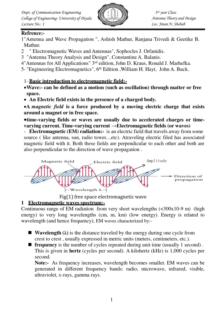
Dept. of Communication Engineering College of Engineering-University of Diyala Lecture No.: 1 3rd year Class Antenna Theoryand Design Lec. Jinan N. Shehab Refrence:- 1"Antenna and Wave Propagation ", Ashish Mathur, Ranjana Trivedi & Geetike B. Mathur. 2 " Electromagnetic Waves andAntennas", Sophocles J. Orfanidis. 3 "Antenna TheoryAnalysis and Design", Constantine A. Balanis. 4"Antennas for All Applications" 3rd edition, John D. Kraus, Ronald J. Marhefka. 5-"Engineering Electromagnetics", 6th Edition ,William H. Hayt, JohnA. Buck. 1-Basic introduction to electromagnetic field:- Wave:- can be defined as a motion (such as oscillation) through matter or free space. An Electric field exists in the presence of a charged body. A magnetic field is a force produced by a moving electric charge that exists around a magnet or in free space. time-varying fields or waves are usually due to accelerated charges or time- varying current.Time-varying current Electromagnetic fields (or waves) - Electromagnetic (EM) radiation:- is an electric field that travels away fromsome source ( like antenna, sun, radio tower....etc). Atraveling electric filed has associated magnetic field with it. Both these fields are perpendicular to each other and both are also perpendicular to the direction of wave propagation . Amplitude Fig(1) free space electromagneticwave 1 Electromagnetic waves spectrum:- Continuous range of EM radiation from very short wavelengths (<300x10-9 m) (high energy) to very long wavelengths (cm, m, km) (low energy). Energy is related to wavelength (and hence frequency), EM waves characterized by:- Wavelength ( ) is the distance traveled by the energy during one cycle from crest to crest , usually expressed in metric units (meters, centimeters, etc.). frequency is the number of cycles repeated during unit time (usually 1 second) . This is given in hertz (cycles per second). A kilohertz (kHz) is 1,000 cycles per second. Note:- As frequency increases, wavelength becomes smaller. EM waves can be generated in different frequency bands: radio, microwave, infrared, visible, ultraviolet, x-rays, gamma rays. 1
Dept. of Communication Engineering College of Engineering-University of Diyala Lecture No.: 1 3rd year Class Antenna Theoryand Design Lec. Jinan N. Shehab Amplitude (A) (m):- The amplitude of the wave is represented by the length of the electrical vector at a maximum or minimum in the wave. Velocity(v or C):- The velocity of a wave is defined as the multiplication of the frequency times the wavelength. This means:- C=V = f in free space (vacuum) =V=C=3 108 m/sec One of the great discoveries in the history of electromagnetism is that electromagnetic waves travel at the speed of light (The velocity of light in vacuum is greater than its velocity in any other medium). Fig.(2) electromagneticSpectrum. Band Abbreviation Audio frequency AF Radio frequency RF Very low frequency VLF Low frequency LF Medium frequency MF High frequency HF Very high frequency VHF Ultra high frequency UHF Super high frequency SHF Extremely high frequency EHF Heat and infrared* Visible spectrum* Ultraviolet* X-rays* Gamma rays* Cosmic rays* Range of frequency 20 to 20,000 Hz 10 kHz to 300,000 MHz 10 to 30 kHz 30 to 300 kHz 300 to 3,000 kHz 3 to 30 MHz 30 to 300 MHz 300 to 3,000 MHz 3,000 to 30,000 MHz 30,000 to 300,000 MHz 106 to 3.9 108MHz 3.9 108 to 7.9 108MHz 7.9 108 to 2.3 1010MHz 2.0 109to 3.0 1013MHz 2.3 1012 to 3.0 1014MHz >4.8 1015MHz Range of wavelength 15,000,000 to 15,000 m 30,000 m to 0.1 cm 30,000 to 10,000 m 10,000 to 1,000 m 1,000 to 100 m 100 to 10 m 10 to 1 m 100 to 10 cm 10 to 1 cm 1 to 0.1 cm 0.03 to 7.6 10-5 cm 7.6 10-5 to 3.8 10-5 cm 3.8 10-5 to 1.3 10-6 cm 1.5 10-5 to 1.0 10-9 cm 1.3 10-8 to 1.0 10-10 cm <6.2 10-12 cm Table (1) Electromagnetic spectrum. (* value approximate) 1-2 Radio frequency (RF) any of the electromagnetic wave frequencies that lie in the range extending from below 3 kilohertz to about 300 gigahertz and that include the frequencies used for communications signals (as for radio and television broadcasting and cell-phone and satellite transmissions) or radar signals.( RF have the longest wavelengths and lowest frequencies of all the electromagnetic waves). Radio propagation :- is the behavior of radio waves when they are transmitted, or propagatedfromonepointontheearthto anther,orintovariouspartsoftheatmosphere. 2
Dept. of Communication Engineering College of Engineering-University of Diyala Lecture No.: 1 3rd year Class Antenna Theoryand Design Lec. Jinan N. Shehab Like light waves, radio waves are affected by the phenomena of reflection, refraction, diffraction, absorption, polarization and scattering. Frequency and wavelength in air <3Hz > 100,000 km 3 30Hz 100,000 km 10,000 km 30 300Hz 10,000 km 1000 km 300 3000Hz 1000 km 100 km 3 30kHz 100 km 10 km 30 300kHz 10 km 1 km Band name Abbreviation Example uses Tremendously low frequency Extremely low frequency Super frequency Ultra frequency Very frequency Low frequency TLF ELF )50-60( low SLF low ULF low VLF , , , ( ) , , LF Medium frequency High frequency MF 300 3000kHz 1 km 100 m 3 30MHz 100 m 10 m , ) ( . HF . Very frequency Ultra frequency Super frequency Extremely high frequency Terahertz Tremendously high frequency high VHF 30 300 10 m 1 m 300 3000 1 m 100 mm 3 30 100 mm 10 mm 30 300 10 mm 1 mm 300 3,000 1 mm 100 m MHz high UHF MHz , , , . , ) , , , ( high SHF GHz , EHF GHz , , or THz or THF GHz , Table (2) radio wave spectrum. 1-3 The electrical properties of the transmission medium:- The transmission media that are used to convey information can be classified as guided or unguided. Guided media provide a physical path along which the signals are propagated; these includetwisted pair, coaxial cable, and optical fiber. Unguided media employ an antenna for transmitting through air, vacuum, or water, then the electrical properties of the transmission medium a- Permittivity ( ) is the measure of the resistance that is encountered when forming an electric field in a medium. In other words, permittivity is a measure of how an electric field affects, and is affected by, a dielectric medium. The permittivity of a medium describes how much electric field (more correctly, flux) is 'generated' per unit charge in that medium. More electric flux exists in a medium with a high 3
Dept. of Communication Engineering College of Engineering-University of Diyala Lecture No.: 1 3rd year Class Antenna Theoryand Design Lec. Jinan N. Shehab permittivity (per unit charge) . each material has certain constant limits the value of permittivity and the permittivity is equal to:- ?= ? ? Where:- 0 = 8.8541878176.. 10 12 F/m is the vacuum permittivity. r is the relative permittivity of the material. This value is different from medium to anther and is equal to one in free space. b. Permeability ( ) also called magnetic permeability, proportionality that exists between magnetic induction and magnetic field intensity. The permeability is equal to: ?= ?0? Where:- ?0 is absolute permeability and is equal to 4 10-7 H/m. ? istherelativepermeabilityofthematerial.Thisvalueis differentfrommedium to anther and is equal to one in free space. c. Conductivity( ) ameasure ofa material's abilityto conductanelectriccurrent. Perfect dielectric has the conductivity is equal to zero approximately. is a constant of 1-4 Optical properties of electromagnetic waves:- a-Reflection (bouncing) When a radio wave propagating in one medium impinges upon another medium having different electromagnetic properties, it will be partially reflected back into the first medium, and partially transmitted (refracted) into the second medium. The basic property of reflection is that the direction of the reflected wave is symmetric to the direction of the incident wave with respect to the surface normal. The rule for reflection is simply stated as: i= r Reflected wave Incident wave First medium Second medium Fig(3) Reflected wave 4
Dept. of Communication Engineering College of Engineering-University of Diyala Lecture No.: 1 3rd year Class Antenna Theoryand Design Lec. Jinan N. Shehab b- Refraction occurs when waves pass from one density medium to another with different velocitiesofpropagation.Theamountofbendingorrefractionthatoccursattheinterface of two materials of different densities is quite predictable and depends on the refractive index which is simply the ratio of the velocity of propagation in a given material (EM wave propagate at the speed of light in a vacuum, in other mediums like air or glass, the speed of propagation is slower). = = The Snell's law connect the relation between the incident wave in the 1st medium and the refracted wave in the second medium n1 sin?1 = 2sin?2 n1= refractive index of first medium. n2= refractive index of second medium. 1= the incident angle. 2= the refracted angle. Refraction (Banding) ? Note:- if the incident medium has a lower index of refraction then the reflected wave has a 180ophase shift upon reflection. Conversely, if the if the incident medium has a large index of refraction then the reflected wave has no phase shift. c- Diffraction (scattring) Scattering (diffraction) is a general interaction process between electromagnetic waves and various objects. Small and irregularly shaped objects, such as trees, lamp posts, street signs or irregularities in building walls are considered as scatterers. The building materials (steel, wire meshes, and plasterboards) cause scattering that in turn causes signal energy to be reradiated in many different directions. d- Interference (colliding) Radio wave interference occurs when two or more eleclromagnetic waves combine in such away to occupy the same position in space using the principle of linear superposition. 5
Dept. of Communication Engineering College of Engineering-University of Diyala Lecture No.: 1 3rd year Class Antenna Theoryand Design Lec. Jinan N. Shehab e. Absorption is the loss of signal power as the signal moves through the transmission medium, and that reduces the available bandwidth. The following two materials are considered the largest absorption for microwaves:- 1 Metals: the electrons in the metals can moving freely through the metal, and then these electrons can swinging and absorbed the electromagnetic waves that pass through the metal. 2 Water: the electromagnetic waves in the water causes jostling the particulars of the water about the electromagnetic waves, and then result in absorption the energy of these waves. 2- Time varying Maxwell's Equation's:- Maxwell s equations describe all (classical) electromagnetic phenomena:- Differential (or Point) Form = ? Integral Form Remarks ? ? . = ? . . = ?. ? = ? + ? . = ? ? ? ? ? . = ? . . = 0 . = 0 Where:- H = magnetic field (A/m). B = magnetic flux density(wb/m2) or Tesla , B= H (?B/?t) = time-derivative of magnetic flux density E = electric field (V/m). D = electric flux density, (C/m2) = E (?D/?t) = displacement electric current density (A/m2)=Jd. 6
Dept. of Communication Engineering College of Engineering-University of Diyala Lecture No.: 1 3rd year Class Antenna Theoryand Design Lec. Jinan N. Shehab ? = volume charge density (C/m3) JT = conduction current density (A/m 2) =Jcond+JSou= ? +J, J= source current 1- Faraday's Law:- Michael Faraday discovered that the induced Vemf (in volts), in any closed circuit is equal to the time rate of change of the magnetic flux linkage by the circuit:- . . = [ ] . . = Lenz s rule gives the direction of the induced emf which states that the induced current produced in a circuit always in such a direction that it opposes the change or the cause that produces it. is the Magnetic Flux within a circuit. e.m.f is the electro-motive force, which is basically a voltage source. (1) The total magnetic flux is simply the integral (or sum) of the B field over the area enclosed by the wire: = ?. = . = ( ) (3) (4) . . ? = . From stokes theorem which can be used to transformthe line integral to the surface integral of curl:- (5) . = . [ ] (6) ? ? ? (2)& (6)? ? (1):- . = . It follows that:- ? = ? Which is the differential form of Faraday's Law. 2- Amper's Law:- For static EM fields, we recall that:- (7) (8) ? ?= ? ( ) But the divergence of the curl of any vector field is identically zero: ?.(? ?) = = ?.? The continuity of current requires that: ( ) 7
Dept. of Communication Engineering College of Engineering-University of Diyala Lecture No.: 1 3rd year Class Antenna Theoryand Design Lec. Jinan N. Shehab ?? ?.?= ? ( ) Thus eqs. 2 and 3 are obviously incompatible for time-varying conditions. We must modify eq. 1 to agree with eq. 3. To do this, we add a term to eq. 1, so that it becomes: ? ?= ?+ ? whereJd is to bedeterminedand defined.Again,thedivergenceofthecurlof anyvector is zero. Hence: ?.(? ?) = = ?.?+ ?.? In order for eq. 5 to agree with eq. 3: ?? ? ? ? Substituting eq. 6 into eq. 3 results in: ( ) ( ) ?? =? (?. ) = ?. ?.? = ?.? ?.? = ( ) ? ? = ? ? = ?+ ? This is Maxwell's equation (based onAmpere's circuit law) for a time-varying field. The term Jd = D/ t is known as displacement current density and J is the conduction and source current density (J = E+J). 3- Poynting Vector and Flow of Power:- Poynting was the developer and eponym of the Poynting vector, which describes the direction and magnitude of electromagnetic energy flow and is used in the Poynting theorem, a statement about energy conservation for electric and magnetic fields, This relation can be obtained from Maxwell's equation as follows:- ? = ? ? Multiply the above equations by dot E and dot H, from these we obtain:- .( ) = .? ? Subtract following vector identity:- = ? +? (1) ? .( ) = ?. + .? (2) ? .( ) .( ) = .( ) We then have:- .( ) = ?. .? .? Next, assume that Ohm's Law applies for the electric current:- (3) (4) ? ? ?= ? (5) .( ) = ?( . ) .? .? (6( ) ) (6( ) ) ? or .( ) = ?| |2 .? .? ? ? ? 8
Dept. of Communication Engineering College of Engineering-University of Diyala Lecture No.: 1 3rd year Class Antenna Theoryand Design Lec. Jinan N. Shehab From calculus (chain rule), we have that:- .? = ?( .? ) = ?1 ? ? ? Hence, we have;- ( . ) .? = ?( .? ) = ?1 ? ? ? ( . ) (7) 2 ? 2 ? ? ? .( ) = ?| |2 ?1 Final differential (point) form of the Poynting theorem: ( . ) ?1 ( . ) (8( ) ) 2 ? ? 2 .( ) = ?| |2 ?(1?| |2) ?(1?| |2) Volume (integral) form (over volume V):- .( ). = ?| |2. ?( (8( ) ) ? 2 2 ? ?| |2) . ?(1?| |2) 1 2 (9) ? 2 ? Using divergence theorem, the last term can be change from avolume integral to a surface integral over the surface S surrounding V, then Final volume form of Poynting theorem:- .( ). = ?| |2. ?( For a stationary surface: . ( ). = ?| |2. ? (( ?| |2)). ? ( ( ?| |2)). ? 2 ?| |2) . ?( 1 2 1 2 ?| |2) . (10) ? ? 1 2 1 (11) ? Power dissipation as heat (Joule's law) Rate of change of stored magnetic energy Rate of change of stored electric energy Right-hand side = power flowing into the volume of space. .( ). =power flowing out of the region. (( ). =power flowing into the region. Define the Poynting vector: W/m2. The Vector S = E X passing through the unit area of surface in unit time normally to the direction of flow of energy. This statement is termed as Poynting s theorem and the vector S is called Poynting Vector. The direction of flow of energy is perpendicular to vectors E and H = H has interpreted as representing the amount of field energy 4-Instantaneous, Average, and Complex Poynting vector:- The time-dependent power flow density of an electromagnetic waveis given by the instantaneous Poynting vector = 9
Dept. of Communication Engineering College of Engineering-University of Diyala Lecture No.: 1 3rd year Class Antenna Theoryand Design Lec. Jinan N. Shehab Consider time-harmonic fields represented in terms of their phasors:- = (1) 1 2[ + ] 1 2[ + ] 2 ( ) = ( ) = (2 ) (2 ) ( ) = ( ) = = Let :- = = Then :- 1 4 1 4 2 + ] (3) [ + ] + [ and = ( ) = and = ( ) = 1 4 1 2 ( ) +2 [ 1 ? 1 1 2 ( ) + 2 ( ) 1 1 ( ) + ( ) cos(2 ) 2 2 1 4 = 2 1 2 ] (4) [ + ] + [ + 2 ] (5) = ? (6) 0 ? 1 1 ? = = ? = ? =2 ( ) 1 ? =2 ( ) Where:- =2( ) Scomis the complex poynting vector. (7) ? 2 0 0 ? (8) 0 (9) 1 (10) 1 10