"Learn about designing electronic circuits for power supplies and voltage regulation. Explore topics such as DC power supplies, Zener diodes, voltage regulators, voltage converters, and isolated voltage supply circuits using transformers, rectifiers, smoothing, and regulation components."
Please find below an Image/Link to download the presentation.
The content on the website is provided AS IS for your information and personal use only. It may not be sold, licensed, or shared on other websites without obtaining consent from the author. If you encounter any issues during the download, it is possible that the publisher has removed the file from their server.
You are allowed to download the files provided on this website for personal or commercial use, subject to the condition that they are used lawfully. All files are the property of their respective owners.
The content on the website is provided AS IS for your information and personal use only. It may not be sold, licensed, or shared on other websites without obtaining consent from the author.
E N D
Presentation Transcript
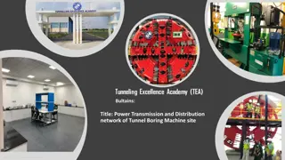
Electronic branch Fourth Class Interface Circuits Design Power Supply Asst. Lec. Lubna A. Alnabi
DC Power Supply The aim of a DC power supply is to provide the required level of DC power to the load using an AC supply at the input. DC power supplies usually have the following parts: Transformer, Rectifier, Smoothing, and Regulation.
power supply using Zener diode The generating a fixed voltage is to use Zener diodes. The regulated voltage can vary from 2.4V to 75V using the BZX79 series diodes. The diodes in this series are rated at 500 mW and the tolerance of the stabilizing voltage is 5%. simplest way of
Voltage Regulator a regulator. It can supply a regulated voltage from 2.85 to 36V with an output current up to 2 A. It features current limiting, thermal shutdown and input over voltage protection up quiescent current is typically 4.2 mA. L200C adjustable voltage to 60V. The
Voltage Converters a voltage inverter which converts +5V voltage to-5V using an SI7660CJ voltage converter (Siliconix). The chip is able to generate a negative voltage output which is equal to the positive voltage input in the range 1.5V to 10V.
Voltage Converters MAX680CPA converts a +5V voltage to +10V and-10V it is doubler and inverter (Maxim). The input voltage ranges from 2V to 6V. The internal resistances for the positive and negative output are 150 ~and 90 respectively. If a 10 mA current is drawn from both outputs, the positive voltage falls to 7V and the negative voltage becomes -6.1V. The quiescent current of the device is typically 1 mA for a 5V power supply.
Isolated voltage supply circuits This circuit is used when a complete isolation between two circuits is required. NME and NMA series DC-to-DC converters are high efficiency voltage converters. The NME series operate from a 5V or 12V DC input and provide an isolated +5V, 12V or 15V output, depending on types. Up to 200 mA supply current is available from the 5V type, 84 mA from the 12V type and 67 mA from the 15V type. The NMA series provide dual +-5V, +-12V and +-15V DC supplies from a single 5V or 12V DC input. Up to 100 mA is available from the 5V type and 42 mA from the 15V type
Digital signal generators an eight-channel logic status generator circuit. It consists of eight single pole double throw (SPDT) switches and eight l k metal film resistors. When a switch is off, the status of the corresponding channel is high. When it is switched on, a logic low is generated. This logic generator suffers that the output signal is not 'clean' when it changes the status. When the switch changes position, the output signal does not change from one state to the other instantly. It consists of a number of oscillations within a very short period of time.
Digital signal generators To solve this problem, a de-bouncing circuit is used. (circuit using a Schmitt trigger inverter, 74LS14). When the switch is closed, the output gives logic 1. When the switch is open, the output gives logic 0. generator circuit with (SPDT)